Intro to Mixing
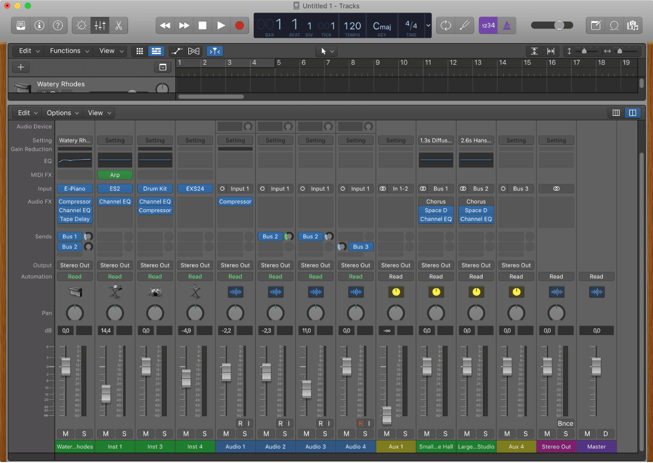
Mixing a project involves balancing the different parts of the project and blending them into a cohesive whole. Most of this is managed in the Mixer view, where you can see all signals and where they're going easily and affect things quickly. Generally, you will need some interaction with the main window, but I would say that you spent 80% of your mixing time in the Mixer window.
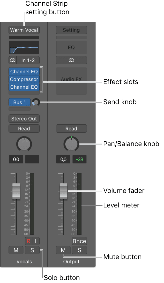
In the Mixer, each track has a channel strip that corresponds to its track type. You can control the sound of the track using its channel strip controls, which include Mute and Solo buttons, a Volume fader and level meter, a Pan/Balance knob, and others. You can also add effect plug-ins, change plug-in settings, and control the signal flow using sends and auxiliary (aux) channel strips.
The channel strip for the currently selected track also appears in the lower-left part of the inspector, along with the channel strip for its output.
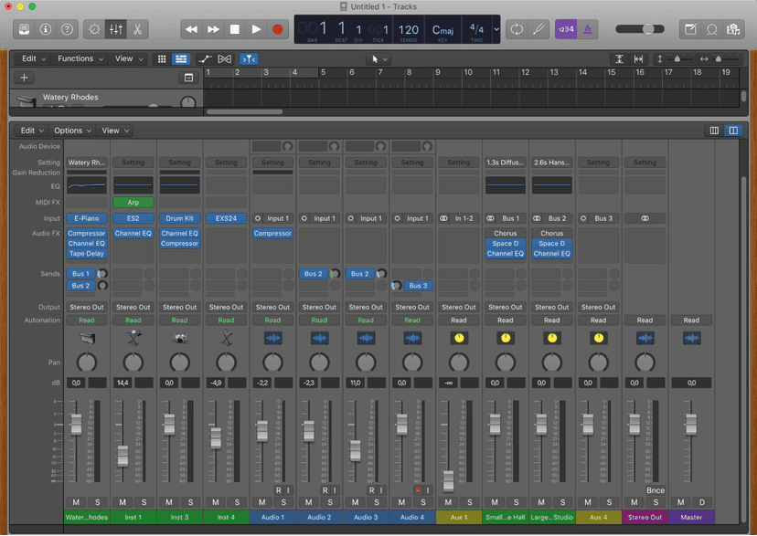
You can of course, see this and more in the Mixer view.
To open the Mixer as a separate window, choose Window > Open Mixer (or press Command-2).
To choose a different Mixer view, do any of the following:
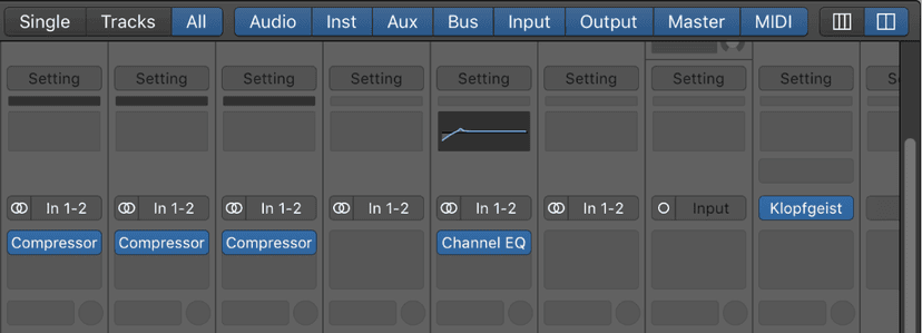
- Click the Single button to show the signal flow of the channel strip that corresponds to the selected track in the Tracks area.
- Click the Tracks button to show the signal flow of all channel strips that correspond to tracks used in the Tracks area.
- Click the All button to show the signal flow of all channel strips available in the project.Note: Aux and output channel strips are examples of channel strips that don’t have a corresponding track in the Tracks area. You can, however, create tracks for such channel strips by choosing Options > Create Tracks for Selected Channel Strips from the Mixer menu bar.
To show or hide Track Stack channel strips, click the disclosure triangle at the bottom of the channel strip in the Mixer.
Make sure that View > Follow Track Stacks is chosen from the Mixer menu bar to mirror the display of Track Stack subtracks in both the Mixer and Tracks area.
When you mix a project, as we said before, you're balancing the different parts and blending them into a whole. You'll also add effects to alter the sound, use routing and grouping to control the signal flow, and use automation to create dynamic changes in your project over time.
Although there are no rules for mixing—except those learned from experience and a good ear—mixing typically involves the following steps. You may find yourself moving back and forth between steps as you work on the mix.
- Setting channel strip volume levels to balance different instruments.
- Setting channel strip pan, or balance, positions to place instruments in the stereo field.
- Adding and adjusting effects and instruments to change the sound characteristics of a track or the overall project.
- Controlling signal flow to create subgroups, route a signal to multiple destinations, or process sounds individually.
- Creating changes over time using automation curves on an individual track or the master track.
In the process of mixing, you can find different ways to accelerate and simplify your workflow, by muting and soloing channel strips, working with channel strip settings and Mixer groups, and customizing the Mixer.
The full scope of Mixing cannot be covered here, which is why we have developed a whole course for it, though going through some of the steps above should help you to see how you can further enhance your productions and make them sound more like finished records!
Channel strip types
You use channel strips to process audio or MIDI information that is routed from tracks. The Mixer shows all channel strips in your project, including track channel strips, auxiliary and output channel strips, VCA channel strips, and the master channel strip.
When you create a new project, the Mixer already includes channel strips for any audio, instrument, and MIDI tracks in your template, as well as the master channel strip and one or more output channel strips depending on your audio interface. As you add audio, instrument, and MIDI tracks to your projects, channel strips are added to the Mixer for each new track.
You can also add Auxiliary and VCA tracks from the Mixer > Options menu.
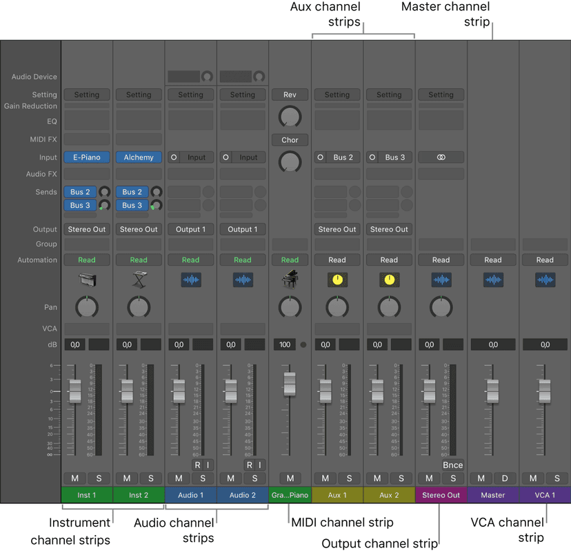
- Audio channel strips: Used to control the playback and recording of audio signals on audio tracks. All data on the audio track is automatically routed to the audio channel strip assigned in the track list.
- Instrument channel strips: Used to control software instruments. Software instruments are inserted via the channel strip’s Instrument slot. The instrument channel strip can then be driven by a recorded MIDI region, or by playing your MIDI keyboard.
- Aux (Auxiliary) channel strips: Used for a variety of signal-routing purposes. Aux channel strips are used to set up send returns, where a channel strip signal is routed to an aux channel strip for effects processing. They are also used for grouping and for distributing a signal to multiple destinations via sends.
- Output channel strips: Represent the physical audio outputs of your audio interface. They are used to adjust the overall level and stereo balance—or pan position, in the case of mono output channel strips—of all audio, instrument, or aux channel strips routed to them. The number of available output channel strips is determined by the audio interface in use.
- VCA channel strips: Represent a VCA group, used to control the volume, or automate a submix, of tracks that are assigned to the VCA fader.
- Master channel strip: Used as a global volume control for all output channel strips. The master channel strip changes the gain of all output channel strips without affecting the level relationships between them. This is helpful as a proportional output volume control and is particularly useful in Logic Pro surround format where you can use it to create fades in the complete surround mix.
- MIDI channel strips: Used to control external MIDI tracks. MIDI data on these tracks is routed to a MIDI output port and channel, for control of MIDI sound modules and keyboards.
Note: Bus and input channel strips are included for compatibility with earlier versions of Logic Pro. Signal routing and other bus channel strip functions are now handled by aux channel strips. Audio hardware inputs are now handled by audio channel strips.
To delete channel strips, select one or more channel strips and press the Delete key.
If the channel strips you wish to delete are assigned to tracks or receiving signal from active busses, a dialog appears informing you that you can choose to delete all the selected channel strips, or to deselect those that are assigned and only delete the remaining channel strips.
To filter channel strips by type, click a filter button to show or hide the channel strip type.

- Option-click a filter button to show that channel strip type; all other channel strip types are hidden.
To select a single channel strip, do one of the following:
- Click on a portion of a channel strip not containing a channel strip control.
- With the Mixer in focus, use the right and left arrow keys to select a channel strip.
When a channel strip is selected, any tracks associated with the selected channel strip are selected in the Tracks area.
To select multiple channel strips, do one of the following:
- Click on a portion of a channel strip not containing a channel strip control and drag the pointer over additional channel strips to add to your selection.
- With a channel strip selected, press the Shift key and use the right and left arrow keys to add additional channel strips to your selection.
When multiple channel strips are selected, any tracks associated with the selected channel channel strips are selected in the Tracks area.
Channel strip controls
Each channel strip has a set of controls (also called components), which varies according to channel strip type. You can adjust the channel strip volume and pan position, mute and solo channel strips, add and adjust effects, and send the output to auxiliary or output channel strips.
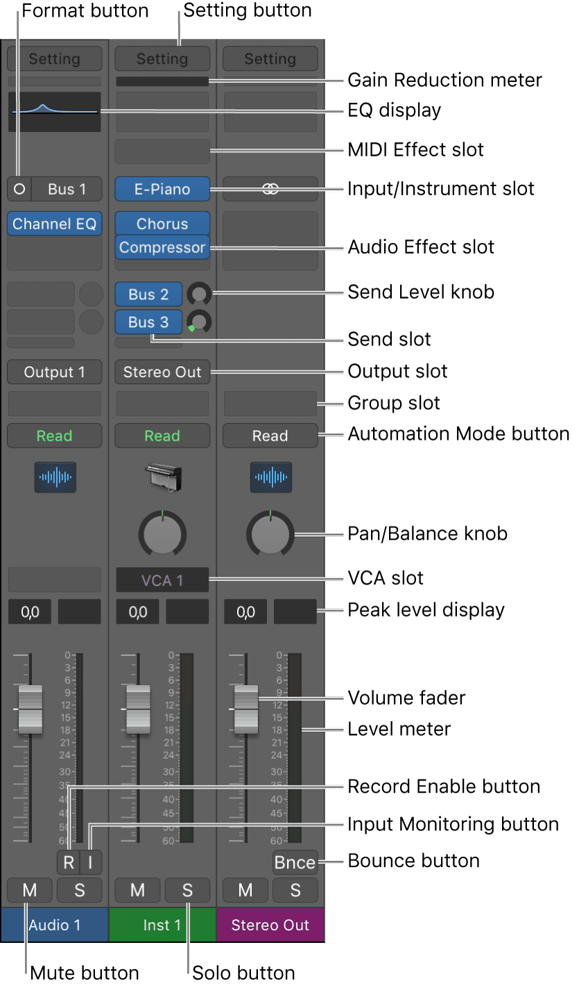
- Setting button: Use to load, browse, or save channel strip settings for the selected track. These settings represent the entire routing configuration of a single channel strip, including plug-ins and their settings.
- Input/Instrument slot: Choose the channel strip’s input source—the input source that your microphone or instrument is connected to.
- Audio Effect slot: Inserts an audio effect into the channel strip. Use effects to alter signals in real time.
- Send slot: Routes the signal to an aux channel strip. The Send Level knob that appears defines the amount of signal to route. Use sends to process effects for multiple signals at the same time.
- Send Level knob: Controls the amount of signal sent to an aux channel strip. Use sends to process effects for multiple signals at the same time.
- Output slot: Choose the channel strip’s output destination—where the channel strip signal is sent to.
- Pan/Balance knob: Sets the channel strip signal’s position. On mono channel strips, it controls the signal’s left/right position. On stereo channel strips, it controls the balance between the left and right signals.
- VCA slot: Assigns the channel strip to an existing VCA group.
- Peak level display: Updates during playback to show the highest peak level reached. A red display indicates signal clipping.
- Volume display: Shows the playback volume.
- Volume fader: Adjusts the playback volume of the channel strip signal.
- Level meter: Shows the level of the input signal—when playing an instrument or singing, for example. Amber and yellow signals are safe. Red indicates signal clipping.
- Mute button: Removes the signal from the overall composition so that it can’t be heard.
- Solo button: Isolates the signal from the overall composition so that it can be heard alone.
- (Input) Format button: Switches the channel strip input format between Mono and Stereo. Click-hold to choose Left, Right, or Surround format.
- Dim button: Turns on Dim Volume mode. This sets the playback volume to the Dim value set in the Logic Pro > Preferences > Audio > General pane.
- Gain Reduction meter: Displays the gain reduction of the first Compressor plug-in in the channel strip. If no compressor is inserted, the meter should display the gain reduction of an inserted Limiter or Adaptive Limiter plug-in.
- EQ display: Click to insert a Channel EQ into the first unused Insert slot, or to open the topmost inserted Channel or Linear Phase EQ. Option-click to insert a Channel EQ into the first slot and move any inserted plug-ins down one slot. Shift-click to insert a Linear Phase EQ into the first unused Insert slot. Option-shift-click to insert a Linear Phase EQ into the first slot and move any inserted plug-ins down one slot. Use EQ effects to shape an audio signal by adjusting specific frequency range levels.
- MIDI Effect slot: Insert a MIDI effect into the channel strip.
- Group slot: Controls a channel strip’s group assignment. Use the Group Settings window to define which parameters are controlled for the entire group at once.
- Automation Mode button: Sets how channel strip and plug-in changes are handled during recording and playback.
- Input Monitoring button: Allows you to hear incoming audio on audio tracks that aren’t armed for recording. Use to set audio levels or to practice parts before recording.
- Record Enable button: Arms the track or channel strip for recording.
- Bounce button: Bounces the output of any output channel strip to an audio file.
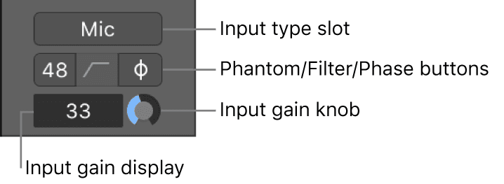
- Audio Device controls: The following audio channel strip controls are only visible when you are using a compatible audio interface.
- Input type slot: Choose the type of audio device connected to the input, for example microphone, instrument, line level equipment, and so on.
- Phantom power button: Sends phantom power to an attached microphone. Check your microphone documentation to determine if your microphone needs phantom power.
- Filter button: Activates a low-cut filter across the input. This can reduce the amount of low-frequency rumble recorded, if present in the source signal.
- Phase reverse button: Use this button to reverse the phase of the audio signal. This can be useful when recording the same signal with multiple microphones. When the button is lit, the phase is reversed.
- Input gain field: Displays the amount of input gain added to the audio signal.
- Input gain knob: Use to set the amount of input gain.
- Direct hardware monitoring button: Activates or deactivates direct hardware monitoring for the channel. This allows you to hear your recorded material without the latency incurred by monitoring your signal through Logic Pro. See your audio interface’s documentation for details on how it impliments direct hardware monitoring.
You can choose which channel strip controls you want displayed on channel strips by doing one of the following:
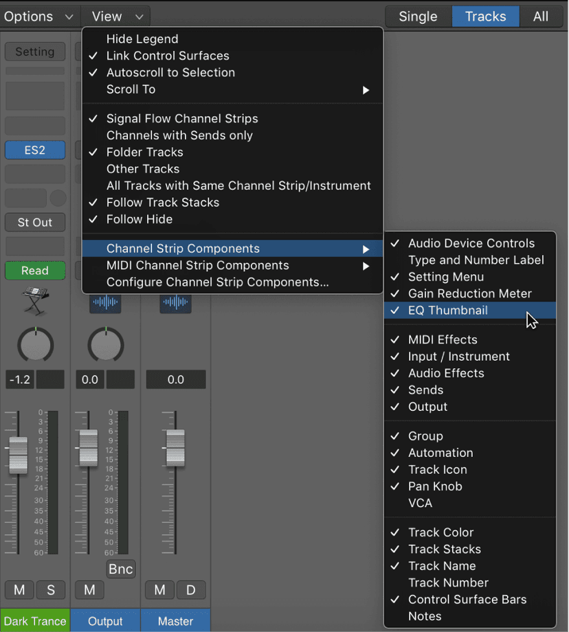
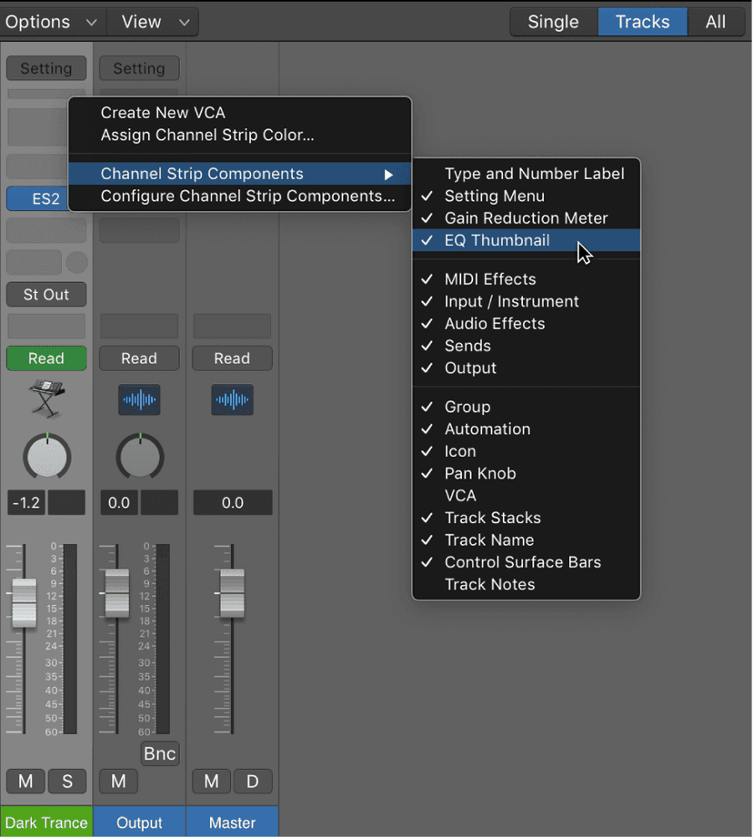
- In the Channel Strip Components or MIDI Channel Strip Components submenus of the Mixer > View menu, choose a control to display, or deselect a control to remove it.
- Control-click a portion of a channel strip not containing a channel strip control and in the Channel Strip Components submenu of the pop-up menu choose a control to display, or deselect a control to remove it from channel strips.
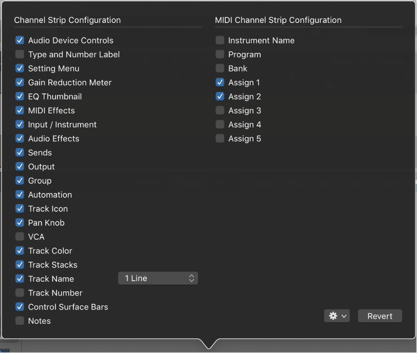
- Choose Configure Channel Strip Components from the Mixer > View menu, the channel strip pop-up menu, or press the Configure Channel Strip Components key command and choose which controls you wish to display.
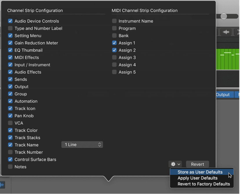
To save a configuration of channel strip controls as default, choose Configure Channel Strip Components from the Mixer > View menu or Control-click a channel strip and choose Configure Channel Strip Components from the pop-up menu.
Choose Store as User Defaults from the Actions menu.
Peak level display and signal clipping
The peak level display is a numerical display located above the level meter. It updates during playback to show the peak level reached, after the entire signal has been played through to the end, and provides a guide that should be used to set the Volume fader.
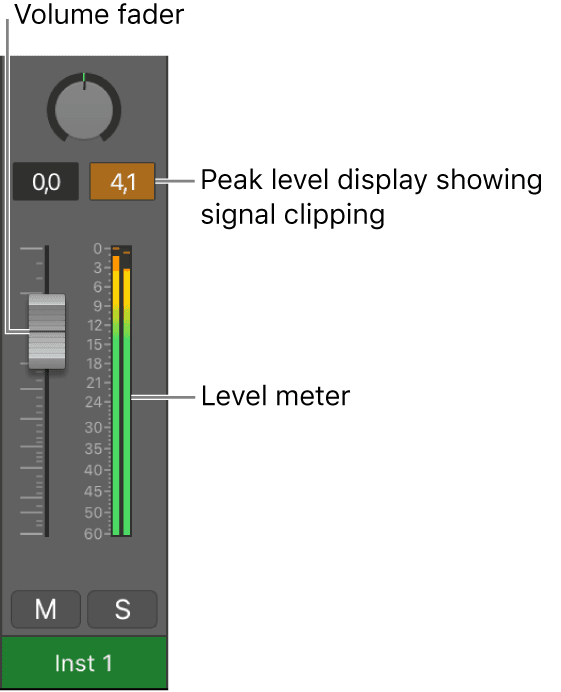
Signal clipping occurs when a signal that is too loud is fed through the output channel strip, thereby exceeding the limit of what can be accurately reproduced, resulting in distorted sound. The value shown in the peak level display lights red when the signal clips. This part of the peak level display is called the clipping indicator.
Note: It’s not an issue if individual channel strips show evidence of clipping, as long as the output channel strip—the summed level of all channel strips in the signal flow—does not indicate clipping.
To avoid clipping, you need to ensure you have audio and instruments that are not too loud!
Setting channel strip input formats
The channel input format determines the mono, stereo, or surround state of the channel strip. The symbol on the button indicates the current state as follows:
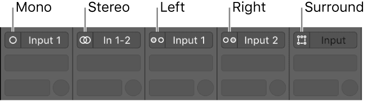
- Mono: One circle represents a mono input format. The level meter shows a single column.
- Stereo: Two interlocked circles represent a stereo input format. The level meter divides into two independent columns when a stereo input format is chosen.
- Left: Two circles, with the left one filled, indicate a left channel input format. Only the left channel of a stereo audio file is played back. The level meter shows a single column.
- Right: Two circles, with the right one filled, indicate a right channel input format. Only the right channel of a stereo audio file is played back. The level meter shows a single column.
- Surround: Five circles indicate the surround channel input format. The level meter divides into multiple linked columns (the number matches the project surround format) when the surround input format is chosen.
To set the channel strip input format, do one of the following:
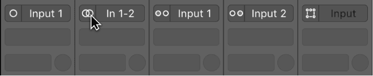
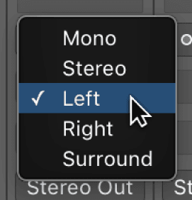
- Click the Format button to switch between mono and stereo input format.
- Click-hold the Format button, then choose an input format from the pop-up menu.
Setting pan or balance positions
Instead of having instruments compete with one another in a mix, you can separate elements by positioning audio and instruments in the stereo mix from left to right. Typically, you want to have the most important tracks (lead vocals, solo instruments, drums, bass) positioned in the center of the mix, and have other tracks (rhythm instruments, instruments doubling the melody) to the sides.
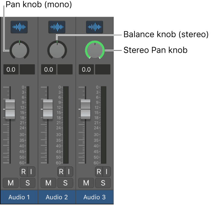
The Pan (short for panorama) knob defines whether a track is heard from the left, right, or center of the stereo field. You can set the pan position for each track in a project. Logic includes several different panning modes. The options available depend on the type of channel strip:
- Pan: This is the default panning mode for mono channel strips. The panner determines the position of a signal in the stereo image. At the center pan position, the channel strip sends equal amounts of the signal to both sides of the stereo image. If you increase the pan position on the left side and decrease it on the right, the sound would move to the left.
- Stereo Pan: The Stereo Pan mode is only available on stereo channel strips. Use this mode to place the position of the left and right signals individually in the stereo field, as if you had two separate pan knobs.
- Balance: This is the default panning mode for stereo channel strips. It differs from Stereo Pan mode in that it controls the relative levels of two signals (Left and Right) at their outputs.
- Binaural: Binaural panning is a method to simulate the full range of spatial information—angle, elevation, and distance—on the panning plane. Binaural panning is best suited for headphone playback.
Mono channel strips have a Pan knob by default. Stereo channel strips have a Balance knob by default.
Signals at the center of the stereo panorama might sound louder than those panned hard right or hard left. To compensate for this perceived increase in volume at the center position, Logic Pro offers numerous options for pan laws, or amounts of volume reduction for signals panned to the center. The Pan Law pop-up menu is in the General Audio Settings.
Note: If you have configured a send to be in Independent Pan mode, the pan knob for that channel strip controls the stereo panorama to the send. The pan options above still apply to the pan knob when controlling a send.
To select a panning mode for a channel strip, control-click the Pan knob, then choose a panner from the shortcut menu.
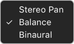
To set the Pan knob or Balance knob position for a channel strip, do one of the following:
- Drag the Pan knob or Balance knob for the channel strip horizontally or vertically.
- Option-click the Pan knob to return it to the center position.
- Press and hold Shift while you drag the knob to change the pan position in finer increments.
To adjust the Stereo Pan knob for a channel strip, do the following:
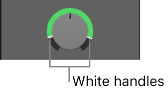
- To adjust the stereo spread of one channel without affecting the other channel, drag the white handle. For example, if you want to narrow the stereo field of the left channel only, drag the white handle of the left channel vertically closer to the center position.
- To invert the right and left channels, Command-click anywhere inside the Stereo Pan knob or ring. The signal ring changes color from green to orange (or back again).
- To widen or narrow the stereo spread range, drag the green or orange ring vertically.
- To adjust the center position of the stereo spread, drag the center of the Stereo Pan knob vertically.
- To reset the stereo spread and center position to their initial values, Option-click anywhere inside the Stereo Pan knob or ring.
Note: When a channel strip output is set to Surround, the knob is replaced by a Surround control.
Insert effects
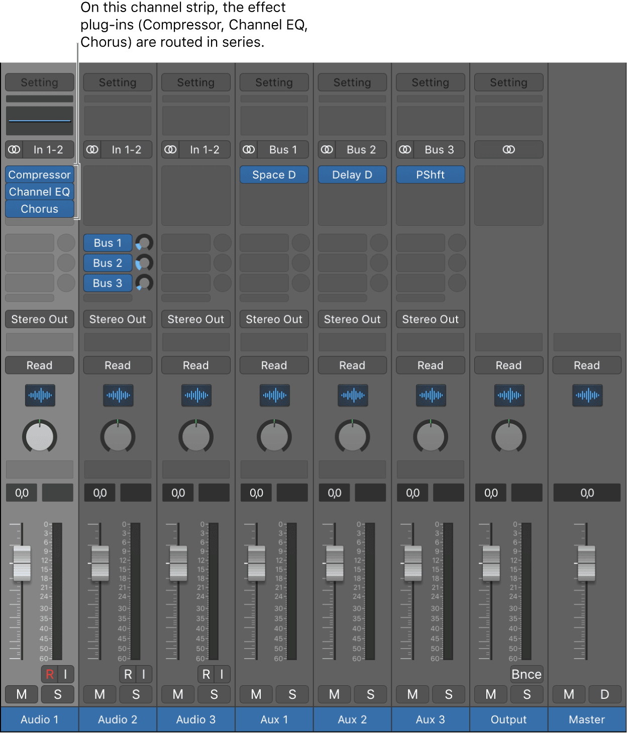
When a plug-in is inserted directly into a channel strip, it is termed an insert effect. The channel strip’s entire signal is processed by the effect plug-in. This behavior is suitable for equalizers or dynamic effects, such as compressors. If you have enough processing capacity, you can use up to 15 insert effects on each channel strip.
When multiple effect plug-ins are routed to a channel strip via inserts, they are said to be routed in series. In this type of configuration, the output of one effect is added to the incoming signal and becomes the input of the next effect in the chain. The image below illustrates this process.
Send effects
You use send effects when you want to isolate effect plug-ins from a channel strip’s signal flow, or when you want to use the same effect on more than one channel strip. By creating a send, you split the channel strip’s signal. The channel strip’s main signal continues its route to the chosen output. The other part of the signal is routed down a parallel path, via a bus to an aux channel strip. You use the Send Level knob to control the amount of signal that is sent via the bus. This is known as parallel routing. You can route the signal back into the main signal flow at a later point, or you can output the signal from the aux channel strip.
The primary advantage of this approach over routing via insert effects is efficiency. This method allows multiple channel strips to be processed by one inserted effect, which saves vast amounts of processing power (and time) when compared to the alternative of inserting the same effect directly into multiple channel strips. Another bonus is that you can quickly switch between wet and dry versions of all channel strips that are sent to an aux channel strip, by simply bypassing the effect on the aux. Similarly, you can completely change the effects configuration for multiple sent channel strips by choosing different effects for the aux channel strip.
The following image illustrates a channel strip routed to multiple aux channel strips via sends—with reverb, chorus, and delay effects assigned to aux channel strips 1, 2, and 3, respectively.
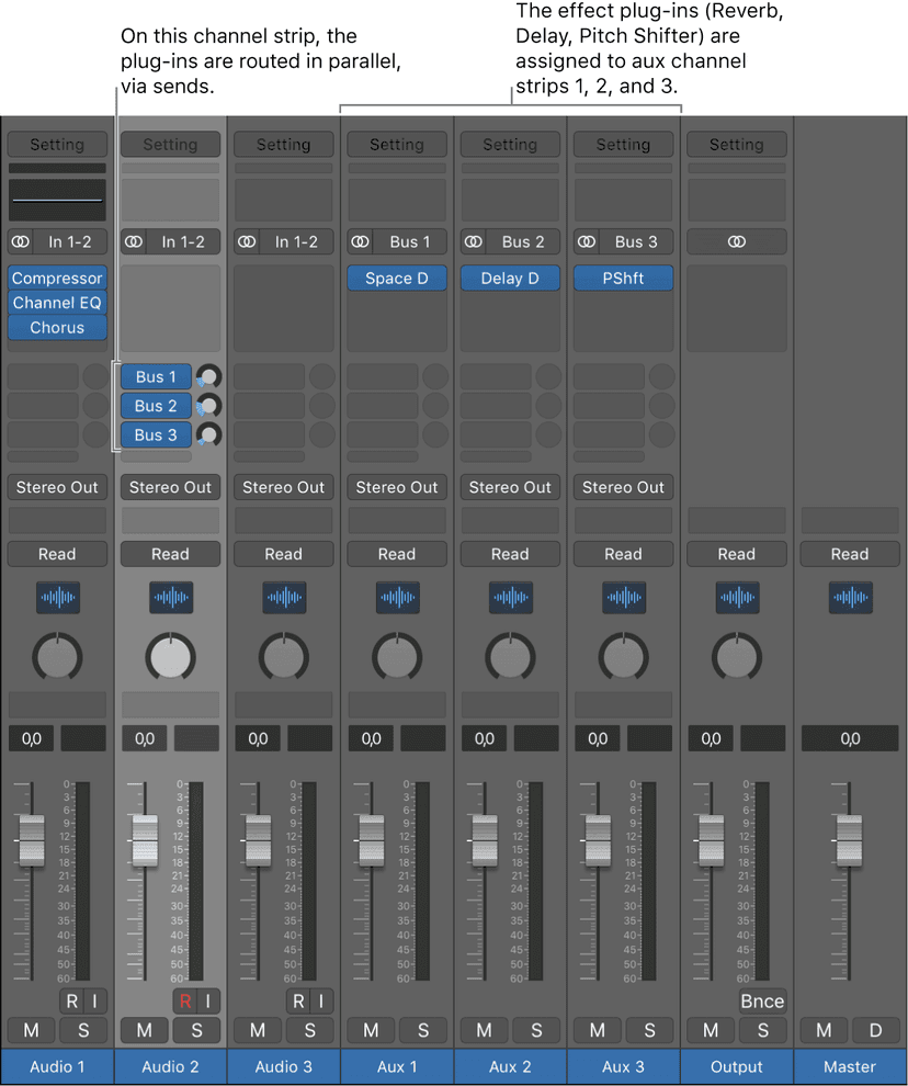
The channel strip signal is split and routed to three separate effects, one on each aux channel strip. These three independent signals are then sent back from the respective aux channel strips and combined into an output stream from the original channel strip. You can create up to eight sends on each audio, instrument, or aux channel strip.
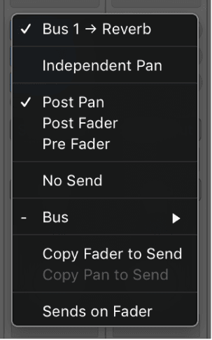
You use the Send pop-up menu to configure where in the channel strip signal the send occurs, and to set the destination for the parallel routing of the send. You have three options for where the send can occur in the signal flow:
- Post Pan: The signal is sent after the fader and the Pan knob; the send signal is affected by adjustments to both channel strip volume and pan adjustments.
- Post Fader: The signal is sent after the fader but before the Pan knob; the send signal is affected by volume adjustments but not pan adjustments.
- Pre Fader: The signal is sent before the fader and Pan knob; the send signal is affected by neither volume nor pan adjustments.
Use the Send pop-up menu to configure where the send occurs, and to set the destination for the send.
Click-hold the Send knob to open the Send pop-up menu.
Choose a destination for a send by choosing a Bus from the submenu of the Send pop-up menu.
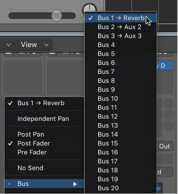
If you have named the aux channel strip that a bus is sending to, the name appears beside the bus number.
To highlight the destination of a send, shift-click the send.
Any aux channel strips to which the send is routing flash three times.
Note: Double-clicking a send doesn’t affect the current selection.
Aux channel strips
Aux channel strips can be used to create subgroups, to submix, to route a signal to multiple destinations, and as additional destination channels for multi-output instruments. Typically, you create aux channel strips as you need them. There are three ways to do this:
- An aux channel strip is created automatically when a send assignment is made from a channel strip, except when the chosen bus is already in use as an input source on another channel strip.
- When a multi-output instrument such as the Sampler is inserted into an instrument channel strip, several aux channel strip assignments are made “behind the scenes.” You then must create the required number of aux channel strips by clicking the Add button (+) at the bottom of the instrument channel strip. Each time you click it, a new aux channel strip is created (and automatically assigned to particular instrument outputs).
- You can also create aux channel strips by choosing Options > Create New Auxiliary Channel Strip from the Mixer menu bar.
Creating mix subgroups
You can group several channel strips and route them via a single bus to a single aux channel strip. This provides you with one set of controls over the entire group.
For example, say your mix contains multiple drum tracks that you want to manage using a single set of channel strip controls, or you want to put a compressor across the whole drum kit. You can do this by sending each of the drum tracks to the same bus, which in turn sends their signals to the same aux channel strip. You might then route your vocal tracks to a second aux channel strip, providing a separate group control for these channel strips. Finally, you have the option to output both subgroups (drums and vocals) to the same destination or to separate destinations.
Note: There are some similarities between using aux channel strips as subgroups and working with Mixer groups. You can control the group/subgroup properties from one set of channel strip controls. However, Mixer groups are used to control channel strip group properties, and not the signal flow.
You can create a subgroup using an aux channel strip. Select multiple channel strips by doing one of the following:
Shift-click the channel strips you want to group.
Drag over the background of the channel strips (drag horizontally across multiple channel strips over the word Inserts, or I/O text, for example).
Click-hold the Output slot of a selected channel strip, then choose a bus from the pop-up menu. The Output slots of all selected channel strips reflect the chosen bus. A new aux channel strip is created, except when the chosen bus is already in use as an input source on another channel strip. Its Input slot contains the channel strip signal flow coming via the chosen bus.
Click-hold the Output slot of the aux channel strip, then choose the output destination for the main mix.
Use the aux channel strip controls to process the submix—adding inserts, setting volume and pan, and so on.
Creating tracks for 'signal flow' channel strips
Signal flow channel strips do not appear in the Tracks area. However, you may want certain signal flow channel strips to appear in the Tracks area if, for example, you want to automate parameters on those channel strips. You can add signal flow channel strips to the Tracks area either as individual tracks or as a Track Stack.
To create individual tracks for signal flow channel strips:
- Select one or more signal flow channel strips.
- Choose Options > Create Tracks for Selected Channel Strips, or press Control-T.
A new channel strip is created in the Tracks area for each of the selected channel strips.
To create a Track Stack for signal flow channel strips:
- Select the signal flow channel strips that you want to be in the Track Stack.
- Choose Options > Create Track Stack for Selected Channel Strips.
A new Track Stack containing all the selected signal flow channel strips is created in the Tracks area, and the selected channel strips are combined into a Track Stack in the Mixer. If you created a Folder Stack, the disclosure triangle in the Mixer is closed by default, and only the Folder Stack channel strip appears. If you created a Summing Stack, the disclosure triangle in the Mixer is open by default, and the selected channel strips appear along with the enclosing Summing Stack auxiliary channel strip.
Groups
Prior to mixing, you may find it useful to define some logical channel strip groups. You could, for example, group all drum channel strips under one drum group. This would allow you to control the group meters (volume, pan, mute, solo, sends, and so on) using a single control, while still maintaining the relative parameter values of each channel strip.
You can also automate a group. This lets you easily set the change for parameters of a group of channel strips over the course of a project. For example, you may wish to group all of your guitar channel strips together and have all of their relative volumes change at the same time throughout your project.
You can have a maximum of 32 groups, and a channel strip can be a member of multiple groups.
It is possible to use aux channel strips for grouping purposes, but with aux channel strips the emphasis is on controlling channel strip signal flow.
You use the Groups inspector to define the behavior of each Mixer group. The Groups inspector appears in the Track inspector when one or more groups have been created, and it can be opened as a floating window as well. It contains the following settings:
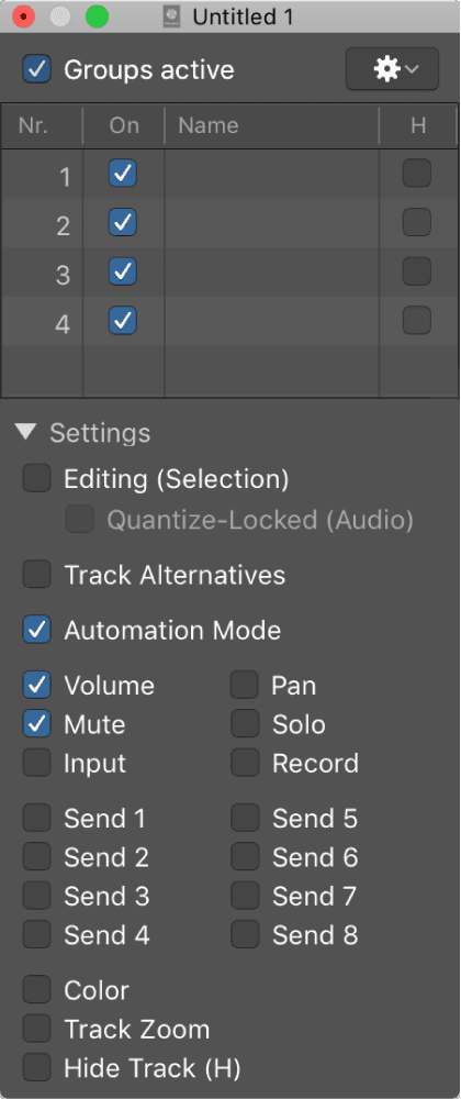
- “Groups active” checkbox: Enables or disables all groups and group controls. Turn off this setting to edit track parameters outside of all groups. Press Command-G to do so when the Group Settings window is closed.
- On checkbox: Enables or disables a particular group. Turn off this setting to edit track parameters outside of the specified group.
- Name field: Shows the group name, which you can create or edit by double-clicking.
- H checkbox: When selected, hides all tracks belonging to the group. If the Hide Track buttons of grouped tracks are in different states, the H checkbox displays “–”.
- Editing (Selection) checkbox: When selected, selecting a region in the Tracks area selects the same horizontal region range of all tracks in the group.
- Quantize-Locked (Audio) checkbox: Defines whether an edit group is phase-locked or independent when quantizing audio.
- Automation Mode checkbox: When selected, changing the automation mode of one track changes the automation mode of all tracks in the group.
- Volume checkbox: When selected, changing the Volume fader of one track changes the volume level of all tracks in the group. The channel strips continue to maintain their relative volume levels.
- Mute checkbox: When selected, changing the mute state of one track changes the mute state of all tracks in the group.
- Input checkbox: When selected, changing the input state of one track changes the input state of all tracks in the group.
- Pan checkbox: When selected, changing the Pan knob of one track changes the Pan knob of all tracks in the group. The channel strips continue to maintain their relative pan positions.
- Solo checkbox: When selected, changing the solo state of one track changes the solo state of all tracks in the group.
- Record checkbox: When selected, changing the record-enabled state of one track changes the record-enabled state of all tracks in the group. Multiple channel strips can be simultaneously record enabled only if they use different inputs.
- Send 1 to 8 checkboxes: When selected, links the Send Level knobs individually for Send slots 1 to 8, while still maintaining the relative positions between them.
- Color checkbox: When selected, changing the color of one track assigns this color to all tracks in the group.
- Track Zoom checkbox: When selected, zooming a region in the Tracks area zooms the regions of all tracks in the group.
- Hide Track (H) checkbox: When selected, selecting the Hide Track button of a grouped track selects the Hide Track buttons of all tracks in the group.
To open the Groups inspector, do one of the following:
- Double-click the header area of the Groups inspector.
- Click the Groups inspector’s disclosure triangle.
- Click the Group slot of a channel strip, then choose Open Group Settings from the pop-up menu.
- Choose Mix > Show Groups.
You can add a channel strip to, or remove a channel strip from, single or multiple groups. You can also temporarily disable all group parameter links—applying a Group Clutch—to change the volume of an individual channel strip, for example.
To add a channel strip to a group, do one of the following:
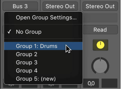
- Click the channel strip’s Group slot, then choose a group from the pop-up menu.
- Select one or more channel strips in the Mixer, then choose Add Selected Channel Strips in the Groups inspector Action pop-up menu.
To add a channel strip to multiple groups, click the channel strip’s Group slot, then press and hold Shift while choosing a group from the pop-up menu.
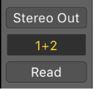
To remove a channel strip from a group, do one of the following:
- Click the Group slot, then choose the group that you want to remove the channel strip from.
- Select one or more channel strips in the Mixer, then choose Remove Selected Channel Strips from the Groups inspector Action pop-up menu.
To remove a channel strip from all groups, click the Group slot, then choose No Group.
To disable all groups, do one of the following:
- Choose Mix > Disable Groups (or press Command-G).
- Choose Options > Disable Groups from the Mixer menu bar.
- Deselect the “Groups active” checkbox in the Group Settings window.
While Group Clutch is active, all Group slots change color, from yellow (normal) to a light gray (all groups temporarily disabled).
Working with channel strip settings
Channel strip settings (CST files) are specific to each channel strip type. Instrument channel strips feature a number of instrument settings, separated into instrument, GarageBand, and Jam Pack categories. Audio channel strips offer effect routings optimized for particular instrument, vocal, and other processing tasks. Similarly, output and auxiliary channel strips provide channel strip settings for particular mastering or sweetening processes.
You can load, copy, paste, reset, save, and delete channel strip settings in a channel strip. You can also access channel strip settings in the Library.
You can remotely switch between channel strip settings by sending MIDI program change messages. This allows you to select your favorite sounds by pushing a button on your MIDI keyboard. To use this feature, you need to save a channel strip setting as a performance.
To load a channel strip setting, do one of the following:
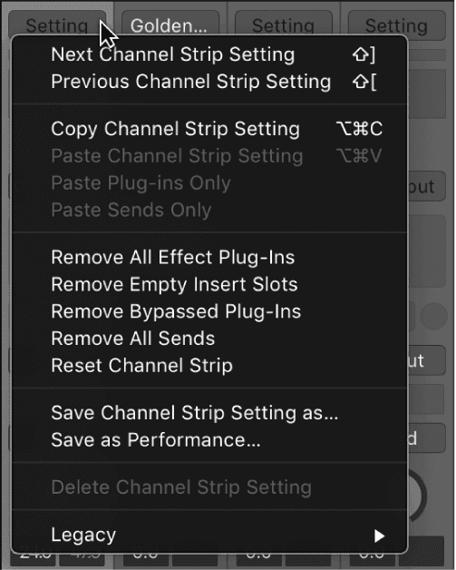
- Click the Setting button at the top of the channel strip, then choose a setting from the pop-up menu.
- Select the relevant channel strip in the Mixer, then click the blue triangle that appears to the left of the Setting button in the inspector channel strip.The Library updates to show channel strip settings, and you can choose the setting you want to add.
Undoing and redoing Mixer and plug-in adjustments
Using the Mixer Undo and Redo commands and the Undo History, you can undo and redo adjustments that you make to channel strips and plug-ins in the Mixer. Undoing or Redoing Mixer and plug-in adjustments is exactly like undoing adjustments in other areas of Logic Pro. The main difference is in the Undo History, where you can choose to include or remove changes from the Mixer and plug-ins from the Undo History action list. If you want to undo changes you make in the Mixer and to plug-ins, make sure that you have the buttons for Include Parameter Changes From for both Mixer and Plug-in turned on.
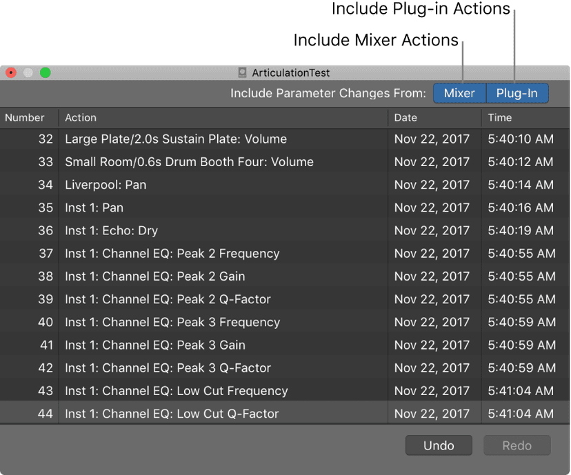
There are also specific Mixer and plug-in undo commands in the Mixer > Edit menu:
- Mixer Undo: Undo last Mixer Action.
- Mixer Redo: Redo last Mixer Action.
- Undo selected Channel Strips: Undo last changes, such as fader adjustments, to the selected channel strips.
- Redo selected Channel Strips: Redo last changes, such as fader adjustments, to the selected channel strips.
- Include Mixer Undo Steps in Project Undo History: Select to include Mixer and plug-in undo steps in the Project Undo History.
- Delete Mixer Undo History: Deletes the Undo History for parameter changes in the Mixer.
Do this now
- Start a mix with every fader down and every plug-in bypassed.
- Bring up the kick, then the bass, then the snare, then everything else, one at a time.
- Do not touch an EQ until the balance is as good as faders alone can make it.
Most mix problems are balance problems. Solve those first and half the EQ moves you were about to make disappear.