Audio FX 4
Dynamics processors
Dynamics processors control the perceived loudness of your audio, add focus and punch to tracks and projects, and optimize the sound for playback in different situations. They're an important part of your Logic effects toolbox to have an understanding of.
The dynamic range of an audio signal is the range between the softest and loudest parts of the signal—technically, between the lowest and highest amplitudes. Dynamics processors enable you to adjust the dynamic range of individual audio files, tracks, or an overall project. This can be to increase the perceived loudness or to highlight the most important sounds, while ensuring that softer sounds are not lost in the mix. Several dynamics processors provide a Side Chain input.
There are four types of dynamics processors. These are each used for different audio processing tasks. Logic Pro X also includes the unique Logic Pro Enveloper, which doesn’t fit any single category.
- Compressors: Downward compressors behave like an automatic volume control, lowering the volume whenever it rises above a certain level, called the threshold.By reducing the highest parts of the signal, called peaks, a compressor raises the overall level of the signal, increasing the perceived volume. This gives the signal more focus by making the louder (foreground) parts stand out, while keeping the softer background parts from becoming inaudible. Compression also tends to make sounds tighter or punchier because transients are emphasized, depending on attack and release settings, and because the maximum volume is reached more swiftly.In addition, compression can make a project sound better when played back in different audio environments. For example, the speakers of a television or in a car typically have a narrower dynamic range than the sound system in a cinema. Compressing the overall mix can help make the sound fuller and clearer in lower-fidelity playback situations.Compressors are typically used on vocal tracks to make the singing prominent in an overall mix. They are also commonly used on music and sound effect tracks, but they are rarely used on ambience tracks.Some compressors—multiband compressors—can divide the incoming signal into different frequency bands and apply different compression settings to each band. This helps to achieve the maximum level without introducing compression artifacts. Multiband compression is typically used on an overall mix.
- Expanders: Expanders are similar to compressors, except that they raise, rather than lower, the signal when it exceeds the threshold. Expanders are used to add life to audio signals.
- Limiters: Limiters (also called peak limiters) work in a similar way to compressors in that they reduce the audio signal when it exceeds a set threshold. The difference is that whereas a compressor gradually lowers signal levels that exceed the threshold, a limiter quickly reduces any signal that is louder than the threshold to the threshold level. The main use of a limiter is to prevent clipping while preserving the maximum overall signal level.
- Noise gates: Noise gates alter the signal in a way that is opposite to that used by compressors or limiters. Whereas a compressor lowers the level when the signal is louder than the threshold, a noise gate lowers the signal level whenever it falls below the threshold. Louder sounds pass through unchanged, but softer sounds, such as ambient noise or the decay of a sustained instrument, are cut off. Noise gates are often used to eliminate low-level noise or hum from an audio signal.
Compressor
Compressor emulates the sound and response of several professional-level compressors. It tightens up your audio by reducing sounds that exceed a certain threshold level, smoothing out the dynamics and increasing the overall volume—the perceived loudness. Compression helps bring the key parts of a track or mix into focus, while preventing softer parts from becoming inaudible. It is probably the most versatile and widely used sound-shaping tool in mixing, next to EQ.
You can useCompressor with individual tracks, including vocal, instrumental, and effects tracks, as well as on the overall mix. Usually you insert Compressor directly into a channel strip, but it can be used on aux channels or elsewhere in the signal path.
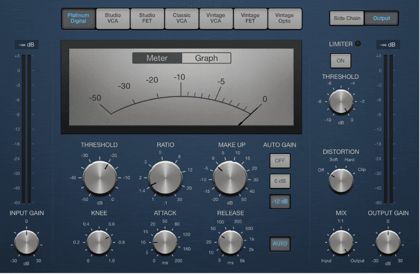
The interface is divided into two main areas:
- Main parameters: The bulk of the interface contains the meters and Threshold, Ratio, Knee, Attack, and other controls.
- Output or Side Chain parameters: The right side of the interface is shared by two discrete groups of parameters. Click the Side Chain or Output button to view and use the parameters in each group.
The main part of the interface contains the core compression parameters. You can choose the type of compressor circuit and can adjust the settings.
Note: Not all parameters listed are available in each Compressor model.
Compressor parameters
- Circuit Type buttons: Choose the type of circuit emulated by Compressor. The interface updates when you choose a model. The choices are Platinum Digital, Studio VCA and FET, Classic VCA, or Vintage VCA, FET, and Opto.
- Platinum Digital: A clean-sounding compression type with a fast transient response. It can be used on a variety of sources.
- FET: Field Effect Transistor compressors are known for their fast transient response. They can deliver a clean or colored tone (notably midrange signals), and can be pushed toward a “crunchy” tone on transients. Ideal for drums, vocals, guitars, and other signals with a fast attack phase. FET compressors can only attenuate the signal.
- VCA: Voltage Controlled Amplifier compressors can respond slowly or quickly to incoming transients. They tend towards a clean tone and are well-suited for bass guitars and low-frequency signals. VCA compressors can attenuate or amplify the signal.
- Opto: Optical compressors are known for their fast transient response and non-linear release handling. They are very clean and are ideal for vocals and guitars. They are also often used as limiting amplifiers across buses or outputs.
- Side Chain and Output buttons: View Side Chain or Output parameters.
- Gain Reduction meter/graph: Click either the Meter or Graph button to change the real-time compression amount display.
- Input Gain knob and field: Set the level at the compressor input.
- Input Gain meter: Displays the level at the compressor input.
- Threshold knob and field: Set the threshold level—signals above this threshold value are reduced in level.
- Ratio knob and field: Set the compression ratio—the ratio of signal reduction when the threshold is exceeded.
- Make Up knob and field: Set the amount of gain applied to the compressed signal.
- Auto Gain buttons: The Off button disables autogain. The 0 dB and -12 dB buttons compensate for volume reductions caused by compression.
- Knee knob and field: Set the strength of compression at levels close to the threshold. Lower values result in more severe or immediate compression (hard knee). Higher values result in gentler compression (soft knee).
- Attack knob and field: Set the time it takes for Compressor to react when the signal exceeds the threshold.
- Release knob and field: Set the time it takes for Compressor to stop reducing the signal after the signal level falls below the threshold. This parameter works in conjunction with the Auto Release function when active.
- Auto Release button: Make the release time dynamically adjust to the audio material. The behavior of the auto release function (and compression results) change when different Release knob values are used.
- Output Gain knob and field: Set the overall level of the compressor output.
- Output Gain meter: Displays the overall level of the compressor output.
DeEsser 2
DeEsser 2 is a frequency-specific compressor, designed to compress a particular frequency band within a complex audio signal. It is used to eliminate sibilance (overly emphasized “s” sounds, especially in vocals, and plosives such as “t” sounds that can be emphasized by compressor and saturation effects) from the signal. DeEsser 2 compresses the signal dynamically, preventing the sound from becoming darker when no sibilance is present. DeEsser 2 has extremely fast attack and release response times for the shortest of transients, thus retaining a natural sound.
DeEsser 2 provides two operating modes that enable you to work with high or low level signals. Also included are two filter shapes and range parameters that are used to define and control the affected frequency range.
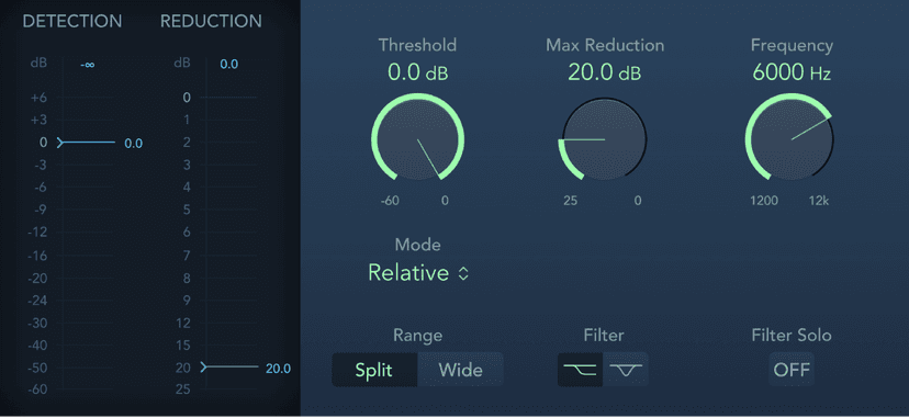
DeEsser 2 parameters
- Detection meter: Shows the input signal level of the selected frequency. Behavior of the meter changes in Absolute or Relative mode. See Mode pop-up menu description.
- Detection max field: The maximum level of the selected frequency is shown. Click to reset.
- Detection meter slider: Drag to set the Threshold, or amplification level, above which gain reduction of the selected frequency is applied.
- Reduction meter: Shows the amount of gain reduction applied.
- Reduction max field: The maximum level is shown (peak hold). Click to reset.
- Reduction meter slider: Drag to set the maximum amount of dynamic gain reduction applied to the selected frequency.
- Threshold knob and field: Set the Threshold, or amplification level, above which gain reduction of the selected frequency is applied.
- Max Reduction knob and field: Set the maximum amount of dynamic gain reduction applied to the selected frequency.
- Frequency knob and field: Set the center or maximum frequency of the detection filter, depending on the chosen filter.
- Mode pop-up menu: Choose Relative or Absolute mode. Relative is the default and works with low and high level signals.
- Relative: In this mode the level of the filtered signal (determined by the Range, Frequency and Filter settings) is compared with the full bandwidth level of the incoming signal. The Threshold parameter value determines the amplification level of the filtered signal (because the level of the filtered signal will always be lower than the full bandwidth signal). When the amplified, filtered signal level is lower than the full bandwidth signal, the Detection meter shows a blue meter below the Threshold value and no processing occurs. When the amplified, filtered signal level is higher than the full bandwidth level, the Detection meter shows a yellow meter above the Threshold value and processing takes place.
- Absolute: The Detection level meter shows the level of the incoming filtered signal (determined by the Range, Frequency and Filter settings). When the level surpasses the Threshold parameter value the meter display switches from blue (not processed) to yellow (processed). Low level signals can only be processed in Absolute mode if the Threshold parameter is set to a very low value.
- Range buttons: Set the filter frequency range. Split affects only signals within the set frequency band. Wide affects the entire frequency range.
- Filter buttons: Choose a lowpass shelving or peak filter shape. The filter is applied before detection.
- Filter Solo button: Turn on to hear the filtered signal—the split frequency band—in isolation, when Split is turned on.
Expander
Expander is similar in concept to a compressor, but increases, rather than reduces, the dynamic range above the threshold level. You can use Expander to add liveliness and freshness to your audio signals.
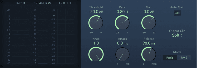
Expander parameters
- Input meter: Shows the input signal level.
- Expansion meter: Shows the amount of gain (expansion) applied to the signal.
- Output meter: Shows the overall output signal level.
- Threshold knob and field: Set the threshold level. Signals above this level are expanded.
- Ratio knob and field: Set the expansion ratio—the ratio of signal expansion when the threshold is exceeded.Note:Because Expander is a genuine upward expander—in contrast to a downward expander, which increases the dynamic range below the Threshold—the Ratio knob features a value range of 1:1 to 0.5:1.
- Gain knob and field: Set the amount of gain.
- Auto Gain button: Turn on to compensate for the level increase caused by expansion. When Auto Gain is active, the signal sounds softer, even when the peak level remains the same.Note: If you dramatically change the dynamics of a signal (with extreme Threshold and Ratio values), you may need to reduce the Gain knob level to avoid distortion. In most cases, turning on Auto Gain adjusts the signal appropriately.
- Knee knob and field: Determine the strength of expansion at levels close to the threshold. Lower values result in more severe or immediate expansion—hard knee. Higher values result in a gentler expansion—soft knee.
- Attack knob and field: Set the time it takes for Expander to respond to signals that exceed the threshold level.
- Release knob and field: Set the time it takes for Expander to stop processing the signal after it falls below the threshold level.
- Output Clip pop-up menu: Choose whether to apply clipping above 0 dB, and the type of clipping. Soft and Hard change the signal around 0 dB in different ways, resulting in a smoothed or squared off distortion of signal peaks.
- Peak/RMS buttons: Determine whether the Peak or RMS method is used to analyze the signal.
Multipressor
Multipressor (an abbreviation for multiband compressor) is a versatile audio mastering tool. It splits the incoming signal into different frequency bands—up to four—and enables independent compression of each band. After compression is applied, the bands are combined into a single output signal.
The advantage of compressing different frequency bands separately is that it allows more compression to be applied to bands that need it, without affecting other bands. This avoids the “pumping” effect often associated with high amounts of compression.
Because the use of higher compression ratios on specific frequency bands is possible, Multipressor can achieve a higher average volume without causing audible artifacts.
Raising the overall volume level can result in a corresponding increase in the existing noise floor. Each frequency band features downward expansion, which lets you reduce or suppress this noise.
Downward expansion works as a counterpart to compression. Whereas a compressor compresses the dynamic range of higher volume levels, the downward expander expands the dynamic range of the lower volume levels. With downward expansion, the signal is reduced in level when it falls below the threshold level. This works in a similar way to a noise gate, but rather than abruptly cutting off the sound, it smoothly fades the volume with an adjustable ratio.
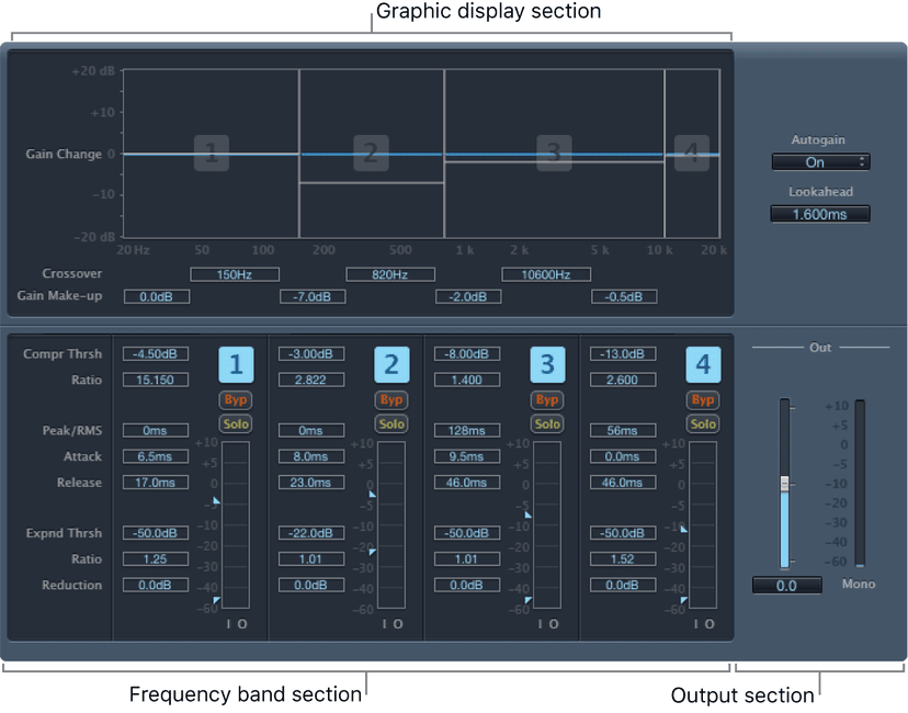
Multipressor parameters are grouped into three main areas: the graphic display in the upper section, the set of controls for each frequency band in the lower section, and the output parameters at the right.
Enveloper
Enveloper is an unusual processor that lets you shape the attack and release phases of a signal—the signal transients, in other words. This makes it a unique tool that can be used to achieve results that differ from other dynamics processors. In contrast to a compressor or expander, Enveloper operates independently of the absolute level of the input signal, but this works only if the Threshold slider is set to the lowest possible value.
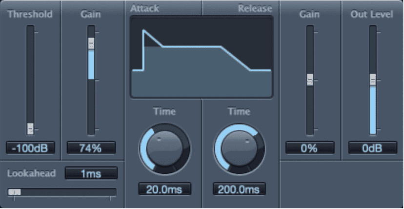
The most important Enveloper parameters are the two Gain sliders, one on each side of the central display. These govern the Attack and Release levels of each respective phase.
Boosting the attack phase can add snap to a drum sound, or it can amplify the initial pluck or pick sound of a stringed instrument. Attenuating the attack causes percussive signals to fade in more softly. You can also mute the attack, making it virtually inaudible. A creative use for this effect is alteration of the attack transients to mask poor timing of recorded instrument parts.
Boosting the release phase also accentuates any reverb applied to the affected channel strip. Conversely, attenuating the release phase makes reverb-drenched tracks sound drier. This is particularly useful when you are working with drum loops, but it has many other applications as well.
Enveloper parameters
- Threshold slider and field: Set the threshold level. Signals that exceed the threshold have their attack and release phase levels altered. In general, set the Threshold to the minimum value and leave it there. Only when you significantly raise the release phase level, which also boosts any noise in the original recording, should you raise the Threshold slider slightly. This limits Enveloper to affecting only the useful part of the signal.
- (Attack) Gain slider and field: Boost or attenuate the attack phase of the signal. When the Gain slider is set to the center position—0%—the signal is unaffected.
- Lookahead slider and field: Set the pre-read analysis time for the incoming signal. The Lookahead slider defines how far into the future of the incoming signal Enveloper looks, to anticipate upcoming events. You generally do not need to use this feature, except when processing signals with extremely sensitive transients. If you do raise the Lookahead value, you may need to adjust the attack time to compensate.
- Display: Shows the attack and release curves applied to the signal.
- (Attack) Time knob and field: Set the time it takes for the signal to increase from the threshold level to the maximum Gain level. Attack Time values of around 20 ms and Release Time values of 1500 ms are a good starting point.
- (Release) Time knob and field: Set the time it takes for the signal to fall from the maximum gain level to the threshold level.
- (Release) Gain slider and field: Boost or attenuate the release phase of the signal. When the Gain slider is set to the center position—0%—the signal is unaffected.
- Out Level slider and field: Set the level of the output signal. Drastic boosting or cutting of either the release or attack phase may change the overall level of the signal. You can compensate for this by adjusting the Out Level slider.
Limiter
Limiter works much like a compressor but with one important difference: where a compressor proportionally reduces the signal when it exceeds the threshold, a limiter reduces any peak above the threshold to the threshold level, effectively limiting the signal to this level.
Limiter is used primarily when mastering. Typically, you apply Limiter as the very last process in the mastering signal chain, where it raises the overall volume of the signal so that it reaches, but does not exceed, 0 dB.
Limiter is designed in such a way that if set to 0 dB Gain and 0 dB Output Level, it has no effect on a normalized signal. If the signal clips, Limiter reduces the level before clipping can occur. Limiter cannot, however, fix audio that is clipped during recording.
Limiter parameters
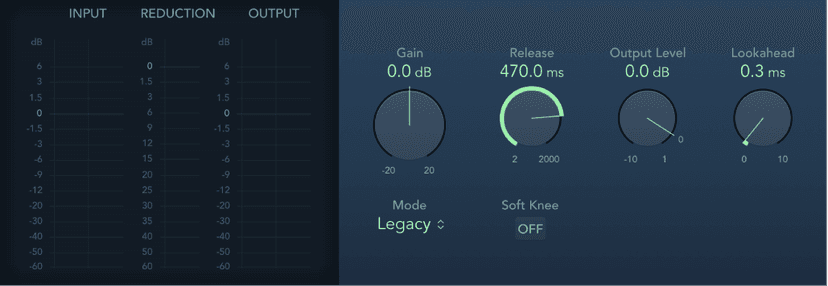
- Input meters: Show input levels in real time. The Margin field shows the highest input level. Click the Margin field to reset it.
- Reduction meter: Shows the amount of limiting in real time.
- Output meters: Show output levels of the limited signal. The Margin field shows the highest output level. Click the Margin field to reset it.Note: The Surround Limiter doesn’t show the Input and Output level meters of mono and stereo variants.
- Gain knob and field: Set the amount of gain applied to the input signal.
- Release knob and field: Set the time it takes for Limiter to stop processing, after the signal falls below the threshold level.
- Output Level knob and field: Set the output level of the signal.
- Lookahead knob and field: Adjust how far ahead (in milliseconds) Limiter analyzes the audio signal. This enables it to react earlier to peak volumes by adjusting the amount of reduction.Note: Lookahead causes latency, but this has no perceptible effect when you use Limiter as a mastering effect on prerecorded material. Set it to higher values if you want the limiting effect to occur before the maximum level is reached, thus creating a smoother transition.
- Mode pop-up menu: Choose between Legacy and Precision algorithms. Use Precision for hard limiting, but be aware that this can introduce distortion artifacts.
- Soft Knee button (Legacy mode): Turn on to limit the signal only when it reaches the threshold. The transition to full limiting is nonlinear, producing a softer, less abrupt effect, and reducing distortion artifacts that can be produced by hard limiting (in Precision mode).
- True Peak Detection button (Precision mode): Turn on to detect inter-sample peaks in the signal.
Adaptive Limiter
Adaptive Limiter is a versatile tool for controlling the perceived loudness of sounds. It works by rounding and smoothing peaks in the signal, producing an effect similar to an analog amplifier being driven hard. Like an amplifier, it can slightly color the sound of the signal. You can use Adaptive Limiter to achieve maximum gain, without introducing unwanted distortion and clipping, which can occur when the signal exceeds 0 dBFS.
Adaptive Limiter is typically used on the final mix, where it can be placed after a compressor, such as Multipressor, and before a final gain control, resulting in a mix of maximum loudness. Adaptive Limiter can produce a louder-sounding mix than can be achieved by normalizing the signal.
Note: Using Adaptive Limiter adds latency when the Lookahead parameter is active. The effect is typically used for mixing and mastering previously recorded tracks, not while recording. Bypass Adaptive Limiter while recording.
Adaptive Limiter parameters
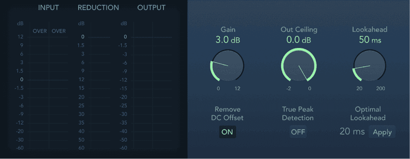
- Input meters: Show input levels in real time. The Margin field shows the peak input level. You can reset the Margin field by clicking it.
- Reduction meter: Show the amount of gain reduction. The Margin field shows the peak reduction level. You can reset the Margin field by clicking it.
- Output meters: Show output levels of the limited signal. The Margin field shows the peak output level. You can reset the Margin field by clicking it.
- Gain knob and field: Set the amount of gain after input scaling.
- Out Ceiling knob and field: Set the maximum output level, or ceiling. The signal does not rise above this.
- Lookahead knob and field: Set the playback buffer size (how far in the future the file is analyzed for peaks). Also see the Optimal Lookahead parameter. Values lower than the optimal buffer size are indicated in red.
- Remove DC Offset button: Turn on to activate a highpass filter that removes direct current (DC) from the signal. DC can be introduced by lower-quality audio hardware.
- True Peak Detection button: Turn on to detect inter-sample peaks in the signal.
- Optimal Lookahead field and button: Use the Apply button to set the optimal playback buffer size. This changes the value shown for the Lookahead parameter.Note: The Optimal Lookahead value is automatically determined and cannot be changed directly.
Noise Gate
Noise Gate is commonly used to suppress unwanted noise that is audible when the audio signal is at a low level. You can use it to remove background noise, crosstalk from other signal sources, and low-level hum.
Noise Gate works by allowing signals above the threshold level to pass unimpeded, while reducing signals below the threshold level. This effectively removes lower-level parts of the signal, while allowing the desired parts of the audio to pass.
In Ducker mode, the source signal is reduced in level. Ducking is a common technique used in radio and television broadcasting. When the DJ or announcer speaks while music is playing, the music level is automatically reduced. When the announcement has finished, the music is automatically raised to its original volume level.
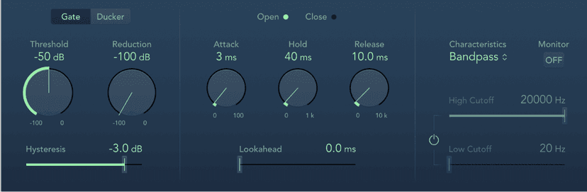
Noise Gate parameters
- Gate/Ducker buttons: Set the operating mode.
- Threshold knob and field: Set the threshold level. Signals that fall below the threshold are reduced in level.
- Reduction/Ducking knob and field: Set the amount of signal reduction.
- Hysteresis slider and field: Set the difference (in decibels) between the threshold values that open and close the gate. This prevents the gate from rapidly opening and closing when the input signal level is close to the threshold level.
- Open/Close indicators: Show current gate state.
- Attack knob and field: Set the time it takes to fully open the gate after the signal exceeds the threshold.
- Hold knob and field: Set the time the gate remains open after the signal falls below the threshold.
- Release knob and field: Set the time it takes to reach maximum attenuation after the signal falls below the threshold.
- Lookahead slider and field: Control how far ahead Noise Gate analyzes the incoming signal, allowing the effect to respond more quickly to peak levels.
- Characteristics pop-up menu: Choose a Bandpass or Band Reject filter type.
- Monitor button: Turn on to hear the side chain signal, including the effect of the High Cut and Low Cut filters (if enabled).
- Filter button: Turn on to adjust the High Cutoff and Low Cutoff parameters.
- High Cutoff slider and field: Set the upper cutoff frequency for the side chain signal.
- Low Cutoff slider and field: Set the lower cutoff frequency for the side chain signal.Note: When no external side chain is selected, the input signal is used as the side chain control signal.
Metering tools
You can use the Metering tools to analyze audio in a variety of ways. These plug-ins provide different views of your audio data that extend the information shown in channel strip meters. The Metering plug-ins have no effect on the audio signal and are intended for use as diagnostic aids.
BPM Counter
BPM Counter analyzes the tempo of incoming audio in beats per minute (bpm). The detection circuit looks for any transients, also known as impulses, in the input signal. Transients are very fast, nonperiodic sound events in the attack portion of the signal. The more obvious this impulse is, the easier it is for BPM Counter to detect the tempo.
Percussive drum and instrumental rhythm parts, such as basslines, are suitable for tempo analysis, whereas pad sounds are unsuitable candidates for tempo analysis.
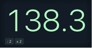
BPM Counter parameters
- BPM Counter: Analyzes the tempo of incoming audio in beats per minute (bpm). Click the numerical display to reset.The numerical display the current analysis status. If the LED is flashing, a tempo measurement is taking place. When the LED is continuously lit, analysis is complete, and the tempo is displayed. The measurement ranges from 80 to 160 beats per minute. The measured value is displayed with an accuracy of one decimal place.Note:BPM Counter also detects tempo variations in the signal and tries to analyze them accurately. If the LED starts flashing during playback, this indicates that BPM Counter has detected a tempo that has deviated from the last received (or set) tempo. As soon as a new, constant tempo is recognized, the LED is solidly lit and the new tempo displayed.
- :2 and x2 buttons: Set the displayed tempo to half or double the analyzed rate.
Correlation Meter
Correlation Meter: Displays the phase relationship of a stereo signal.

- A correlation of +1 (the far right position) means that the left and right channels correlate 100%—they are completely in phase.
- A correlation of 0 (the center position) indicates the widest permissible left/right divergence, often audible as an extremely wide stereo effect.
- Correlation values lower than 0 indicate that out-of-phase material is present, which can lead to phase cancelations if the stereo signal is combined into a monaural signal.
Correlation Meter parameter
- View pop-up menu: Choose a Horizontal or Vertical display and set a size.Note: You can also set a size by dragging the lower corners of the plug-in window.
Loudness Meter
Loudness Meter shows the momentary, short-term, and integrated loudness levels. Loudness indicates the perceived level of a signal that is indicative of human hearing, making it a useful reference tool when mixing or mastering. Loudness Meter conforms to the AES 128 specification.
Loudness is measured in Loudness Units, relative to Full Scale (LUFS). Each LU is equivalent to one decibel.
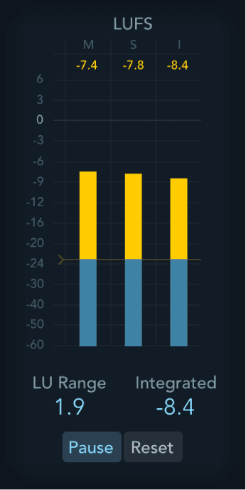
Loudness Meter parameters
- M, S, and I fields and meters: Indicate the current momentary, short-term, and integrated signal levels of incoming program material. The signal level for each channel is represented by a blue bar. Signals approaching the 0 dB level (target level) are represented by a yellow bar. When the level exceeds 0 dB, the portion of the bar above the 0 dB point turns red.
- Target level line: Drag to set a target level.
- LU Range field: Indicates the loudness range during measurement (using the Start/Pause button).
- Integrated field: Indicates the integrated loudness level during measurement (using the Start/Pause button).
- Start/Pause button: Turn on to analyze and show the Integrated Loudness and the LU Range for a portion or the full length of the material. Pause retains the current LU Range and Integrated values.
- Reset button: Clear all values.
- View pop-up menu: Choose a Horizontal or Vertical display and set a size.Note: You can also set a size by dragging the lower corners of the plug-in window.
Level Meter
Level Meter: Displays the current signal level on a decibel scale. The signal level for each channel is represented by a blue bar. Signals (above the target level) approaching the 0 dB level are represented by a yellow bar. When the level exceeds 0 dB, the portion of the bar above the 0 dB point turns red.
Stereo Level Meter instances show independent left and right bars, whereas mono instances display a single bar.
Surround Level Meter instances display a bar for each channel.
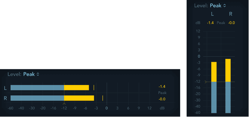
Peak level values are displayed numerically and graphically. You can reset these values by clicking in the display.
Level Meter parameters
- Level pop-up menu: Choose a display setting using Peak, RMS, Peak & RMS, True Peak, or True Peak & RMS characteristics.
- The True Peak options display interpolated sample values.
- RMS levels appear as dark blue bars. Peak levels appear as light blue bars. You can also choose to view both Peak and RMS levels simultaneously.
- Target level handle: Drag to set a target level. Signals above this level and below 0 dB are shown in yellow. Surround instances provide discrete handles for center and LFE, with all other channels controlled by a single handle.
- View pop-up menu: Choose a Horizontal or Vertical display and set a size.Note: You can also set a size by dragging the lower corners of the plug-in window.
Peak and RMS levels
The peak value is the highest level that the signal will reach. The RMS (root mean square) value is the effective value of the total signal. In other words, it is a measurement of the continuous power of the signal.
Human hearing is optimized for capturing continuous signals, making our ears RMS instruments, not peak reading instruments. Therefore, using RMS meters makes sense most of the time. Alternatively, you can use both RMS and Peak meters.
MultiMeter
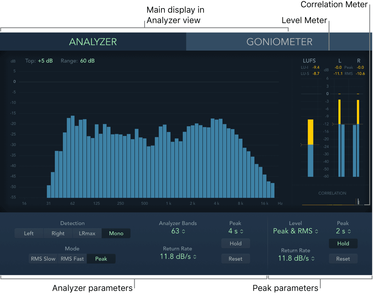
MultiMeter provides a collection of professional gauge and analysis tools in a single window. It includes:
- An Analyzer to view the level of each 1/3-octave or major second frequency band.
- A Goniometer for judging phase coherency in a stereo sound field.
- Level and Loudness Meters to view the signal level and perceived loudness (conforming to the AES 128 specification) for each channel.
- A Correlation Meter to spot mono phase compatibility.
- Peak parameters.
You can view either the Analyzer or Goniometer results in the main display area. Use the Analyzer or Goniometer buttons to switch between modes and to set parameters. The Loudness/Level and Correlation meters are always visible in the Full display, as are several common parameters.
You can set a size by dragging the lower corners of the plug-in window. The View pop-up menu provides further Display, Meters, or Full items that show a partial view or the complete plug-in interface. Control-click in the main display when a partial view is enabled to switch between modes.
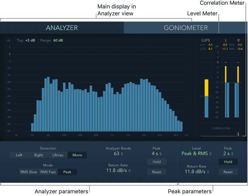
Although you can insert MultiMeter directly into any channel strip, it is more commonly used in the master channel strip of Logic Pro X—when you are working on the overall mix.
Imaging processors
The imaging processors are tools for manipulating the stereo image. You can use them to make certain sounds, or the overall mix, seem wider and more spacious. You can also alter the phase of individual sounds within a mix to enhance or suppress particular transients.
Stereo Spread
Stereo Spread is generally used when mastering. There are several ways to extend the stereo base (or the perception of space), including using reverbs or other effects and altering the signal phase. These options can sound good, but they can also weaken the overall sound of your mix by ruining transient responses, for example.
Stereo Spread extends the stereo base by distributing a selectable number of frequency bands from the middle frequency range to the left and right channels. This is done alternately—middle frequencies to the left channel, middle frequencies to the right channel, and so on. This greatly increases the perception of stereo width without making the sound totally unnatural, especially when it is used on mono recordings.
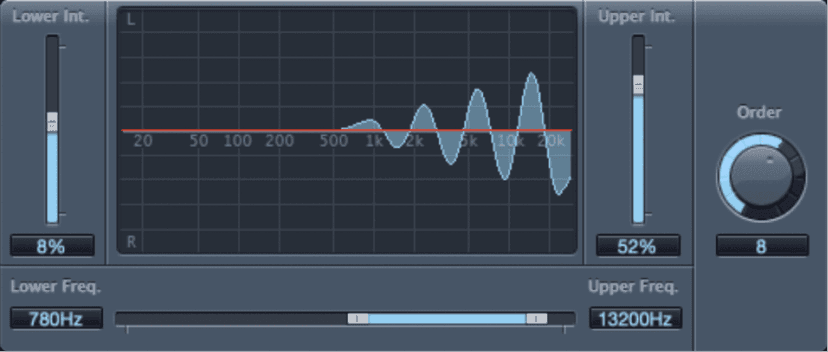
Stereo Spread parameters
- Lower Intensity slider and field: Set the amount of stereo base extension for the lower frequency bands.
- Upper Intensity slider and field: Set the amount of stereo base extension for the upper frequency bands.Note: When setting the Lower Int and Upper Int sliders, be aware that the stereo effect is most apparent in the middle and higher frequencies. Distributing low frequencies between the left and right speakers can significantly alter the energy of the overall mix. Use low values for the Lower Int parameter and avoid setting the Lower Freq parameter below 300 Hz.
- Graphic display: Shows the number of bands the signal is divided into and the effect intensity in the upper and lower frequency bands. The upper section represents the left channel. The lower section represents the right channel. The frequency scale displays frequencies in ascending order, from left to right.
- Upper/Lower Frequency slider and fields: Determine the highest and lowest frequencies that are redistributed in the stereo image.
- Order knob and field: Determine the number of frequency bands that the signal is divided into. A value of 8 is usually sufficient for most tasks, but you can use up to 12 bands.
Direction Mixer
You can use Direction Mixer to decode middle and side audio recordings or to spread the stereo base of a left/right recording and determine its pan position.
Direction Mixer works with any type of stereo recording, regardless of the miking technique used. For information about the most common stereo miking techniques—AB, XY, and MS—see Stereo miking techniques.
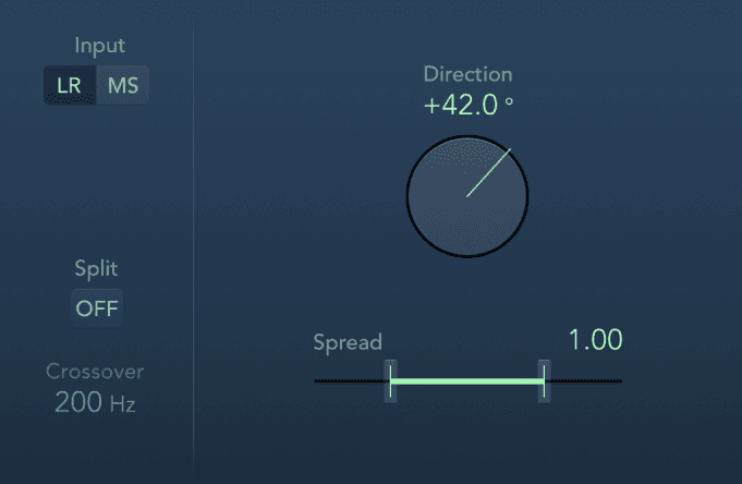
Direction Mixer parameters
- Input buttons: Set the input signal type. Use LR if the input signal is a standard left/right signal. Use MS if the signal is middle and side encoded.
- Direction knob and field: Set the pan position for the middle—the center of the stereo base—of the recorded stereo signal. When Direction is set to a value of 0, the midpoint of the stereo base in a stereo recording is perfectly centered within the mix.When you work with LR signals:
- At 90°, the center of the stereo base is panned hard left.
- At −90°, the center of the stereo base is panned hard right.
- Higher values move the center of the stereo base back toward the center of the stereo mix, but this also has the effect of swapping the stereo sides of the recording. For example, at a value of either 180° or −180°, the center of the stereo base is dead center in the mix, but the left and right sides of the recording are swapped.
- When you work with MS signals:
- At 90°, the middle signal is panned hard left.
- At −90°, the middle signal is panned hard right.
- Higher values move the middle signal back toward the center of the stereo mix, but this also has the effect of swapping the side signals of the recording. For example, at a value of either 180° or −180°, the middle signal is dead center in the mix, but the left and right sides of the side signal are swapped.
- Spread slider and field: Determine the spread of the stereo base in LR input signals or set the side signal level in MS input signals. Spread parameter behavior changes when fed LR or MS signals. These differences are outlined below:When you are working with LR signals:
- At a neutral value of 1, the left side of the signal is positioned precisely to the left and the right side precisely to the right. As you decrease the Spread value, the two sides move toward the center of the stereo image.
- A value of 0 produces a summed mono signal—both sides of the input signal are routed to the two outputs at the same level. At values greater than 1, the stereo base is extended out to an imaginary point beyond the spatial limits of the speakers.
- When you are working with MS signals:
- Values of 1 or higher increase the level of the side signal, making it louder than the middle signal.
- At a value of 2, you hear only the side signal.
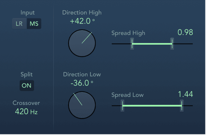
- Split button: Split the signal into independently controlled high and low ranges.
- Crossover field: Set the frequency where the signal is split between high and low ranges. To type a value, drag vertically or double-click.
- Direction High/Low knobs and fields: Independently set the central pan position for the recorded stereo signal in the upper or lower frequency range (set with Crossover).
- Spread High/Low sliders and fields: Independently set the stereo spread in LR signals or set the side signal level in MS signals for the upper/lower frequency range (set with Crossover).
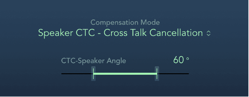
Binaural Post-Processing
Each channel strip allows you to use a special version of the Pan knob, known as Binaural Pan. This is a psychoacoustic processor that can simulate arbitrary sound source positions—including up and down information—when fed a standard stereo signal.
The output signal that results when you use Binaural Pan is best suited for headphone playback. You can, however, use the integrated conditioning of Binaural Pan to ensure a neutral sound that is suitable for speaker playback as well as headphone playback.
Do this now
- Put a Compressor on a vocal. Set the ratio to 3:1 and pull the threshold down until the meter shows 3 to 6 dB of reduction on the loudest lines.
- Now switch the circuit model through all seven without changing anything else.
- Add DeEsser 2 in front of it and find the sibilance rather than guessing.
Same settings, seven different sounds. The model is a tone control, not a detail.