Audio FX 3
Reverb effects
You can use reverb effects to simulate the sound of acoustic environments such as rooms, concert halls, caverns, or an open space.
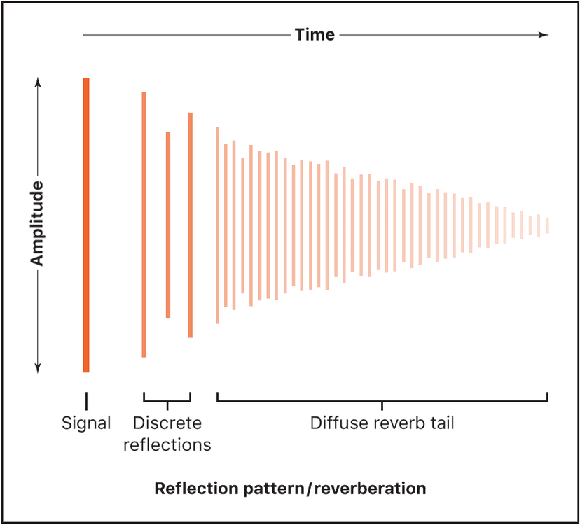
Sound waves repeatedly bounce off the surfaces—walls, ceilings, windows, and so on—of any space, or off objects within a space, gradually dying out until they are inaudible. These bouncing sound waves result in a reflection pattern, more commonly known as a reverberation (or reverb).
The starting portion of a reverberation signal consists of a number of discrete reflections that you can clearly discern before the diffuse reverb tail builds up. These early reflections are essential in human perception of spatial characteristics, such as the size and shape of a room.
Plates, digital reverb effects, and convolution reverb
The first form of reverb used in music production was actually a purpose-built room with hard surfaces, called an echo chamber. It was used to add echoes to the signal. Mechanical devices, including metal plates and springs, were also used to add reverberation to the output of musical instruments and microphones.
Digital recording introduced digital reverb effects, which consist of thousands of delays of varying lengths and intensities. The time differences between the original signal and the arrival of the early reflections can be adjusted by a parameter known as predelay. The average number of reflections in a given period of time is determined by the density parameter. The regularity or irregularity of the density is controlled with the diffusion parameter. Included among the digital reverbs are the unique Logic Pro EnVerb and ChromaVerb.
Computers make it possible to sample and analyze the reverb characteristics of real spaces, using convolution reverbs. These room characteristic sample recordings are known as impulse responses.
Convolution reverbs work by convolving (combining) an audio signal with the impulse response recording of reverb characteristics for a given space.
EnVerb
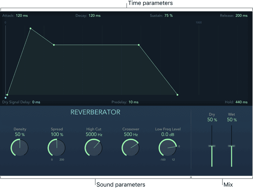
EnVerb is a versatile reverb effect with a unique feature: it allows you to adjust the envelope—the shape—of the diffuse reverb tail. EnVerb is divided into two areas:
- Time parameters: The graphic display shows and lets you adjust levels over time (the envelope) of the reverb. You can control the delay time of the original signal and can change the reverb tail over time.
- Sound parameters: The controls below the envelope display shape the sound of the reverb signal. You can split the incoming signal into two bands with the Crossover parameter and can set the low frequency band separately.
EnVerb time parameters
Drag parameter handles directly in the envelope display, or drag vertically in parameter fields to adjust EnVerb values.
- Attack handle and field: Set the time it takes for the reverb to climb to its peak level.
- Decay handle and field: Set the time it takes for the level of the reverb to drop from its peak to the sustain level.
- Sustain (Hold) handle and field: Drag vertically to set a constant reverb level for the sustain phase. It is expressed as a percentage of the full-scale volume of the reverb signal. See Hold parameter.
- Release handle and field: Set the time it takes for the reverb to fade out completely, after the sustain phase.
- Dry Signal Delay handle and field: Determine the delay of the original signal. Set a suitable level with the Dry slider in the Mix section.
- Predelay field: Set the time between the original signal and the start point of the reverb attack phase—the very beginning of the first reflection.
- Hold (Sustain) handle and field: Drag horizontally to set the duration of the reverb sustain phase. See Sustain parameter.
EnVerb sound parameters
- Density knob and field: Set the reverb density.
- Spread knob and field: Control the width of the reverb stereo image. At 0% the effect generates a monaural reverb. At 200% the stereo base is artificially expanded.
- High Cut knob and field: Filter frequencies above the set value out of the reverb tail.
- Crossover knob and field: Set the frequency used to split the input signal into two frequency bands for independent processing.
- Low Freq Level knob and field: Set the relative level of (reverb signal) frequencies below the crossover frequency. In most cases you get better-sounding results when you set negative values for this parameter.
- Dry/Wet sliders and fields: Determine the balance between the effect (wet) and direct (dry) signals.
ChromaVerb
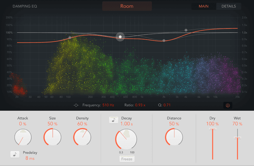
ChromaVerb features fourteen discrete room type algorithms.
The fundamental approach behind ChromaVerb diverges from other methods of reverb creation. It is based on the principle of a circular structure in which the sound is gradually absorbed, much like in a real room. The absorption characteristics are dependent on the chosen room type and reverb parameter settings.
Each room type offers a unique tonal color, ranging from dense rooms to wide spaces and large halls.
The ChromaVerb interface is divided into two windows:
- Main window: Shows common reverb parameters such as Attack, Size, Density, Distance, and Decay. A visualization of the reverb output is shown in a graphic display which allows you to directly edit damping factors, thus changing decay frequencies and dependencies.
- Details window: Provides access to advanced parameters such as Width, Quality, and Modulation. The graphic display shows an editable Output EQ that you can use to shape the ChromaVerb output signal.
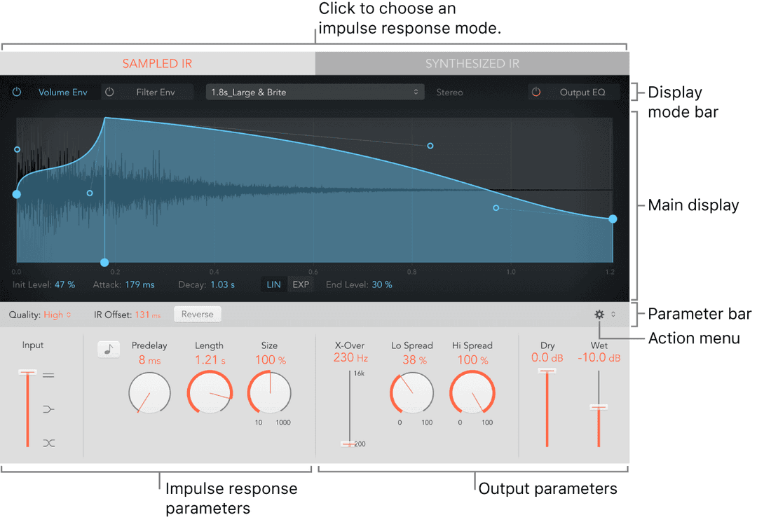
Space Designer
Space Designer is a convolution reverb effect that you can use to place your audio signals in exceptionally realistic recreations of real-world acoustic environments. Space Designer generates reverb by convolving, or combining, an audio signal with an impulse response reverb sample. An impulse response is a recording of reverb characteristics, or more precisely, a recording of all reflections in a given room following an initial signal spike. The actual impulse response file is a standard audio file.
To understand how this works, imagine a situation where Space Designer is used on a vocal track. An impulse response file recorded in an actual opera house is loaded into Space Designer. This impulse response file is convolved with your vocal track, placing the singer inside the opera house.
Convolution can be used to place your audio signal inside any space, including a speaker cabinet, a plastic toy, a cardboard box, and so on. All you need is an impulse response recording of the space.
In addition to loading impulse responses, Space Designer includes an on-board impulse response synthesis facility. This enables the creation of completely unique effects, particularly when the synthesized impulse response doesn’t represent a real space.
Space Designer also offers features such as envelopes, filters, Output EQ, and stereo/surround balance controls, which provide precise control over the dynamics, timbre, and length of the reverberation.
Space Designer can operate as a mono, stereo, true stereo (meaning each channel is processed discretely), or surround effect.
The Space Designer interface consists of the following main sections:
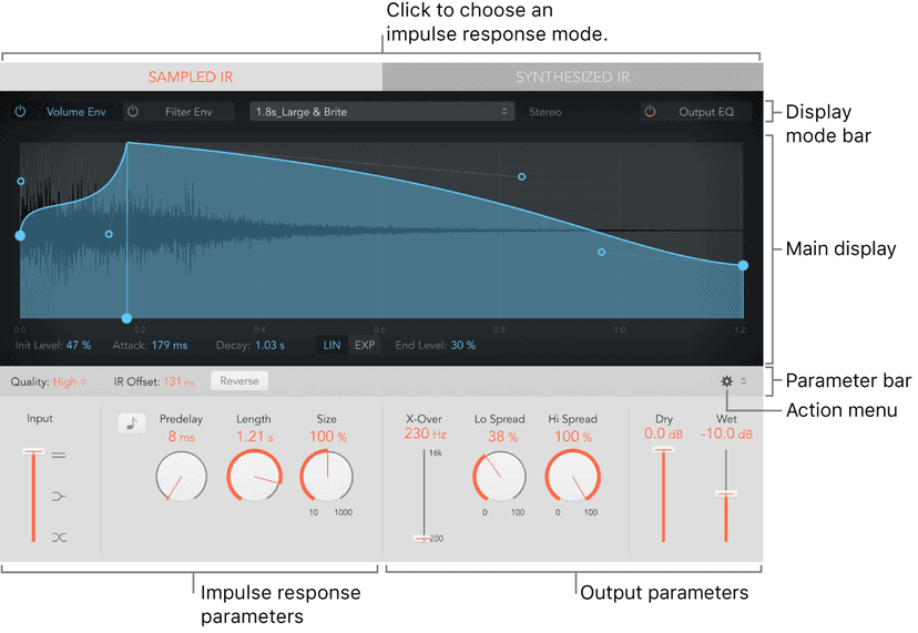
- Impulse response parameters: Use to load, save, or manipulate recorded or synthesized impulse response files. The chosen impulse response file determines what Space Designer uses to convolve with your audio signal.
- Envelope, filter, and EQ parameters: Use the buttons in the display mode bar to switch the main display and parameter bar between envelope, filter, and EQ views. Use the main display to edit parameters graphically, or use the parameter bar to edit them numerically.
- Global parameters: After your impulse response is loaded or generated, use these parameters to determine how Space Designer operates on the overall signal and impulse response. Included are input and output parameters, predelay, and more.
Equalizers
An equalizer (commonly abbreviated as EQ) shapes the sound of incoming audio by changing the level of specific frequency bands.
Equalization is one of the most-used audio processes, both for music projects and in post-production work for video. You can use EQ to subtly or significantly shape the sound of an audio file, an instrument, a vocal performance, or a project by adjusting specific frequencies or frequency ranges.
All EQs are specialized filters that allow certain frequencies to pass through unchanged while raising (boosting) or lowering (cutting) the level of other frequencies. Some EQs can be used in a “broad-brush” fashion, to boost or cut a large range of frequencies. Other EQs, particularly parametric and multiband EQs, can be used for more precise control.
The simplest types of EQs are single-band EQs, which include low cut and high cut, lowpass and highpass, shelving, and parametric EQs.
Multiband EQs such as Channel EQ or Linear Phase EQ combine several filters in one unit, enabling you to control a large part of the frequency spectrum. Multiband EQs let you independently set the frequency, bandwidth, and Q factor of each frequency spectrum band. This provides extensive and precise tone-shaping of any audio source, be it an individual audio signal or an entire mix.
Some EQs, particularly vintage units, are known for the distinctive sonic coloration they impart on the sound.
Other EQs allow you to analyze incoming audio to capture a sonic “fingerprint” which you can then apply to other audio material.
Single-Band EQ
Single-Band EQ can operate in several modes. When you choose an EQ type with the EQ Mode buttons, the controls shown below the buttons update to provide functions appropriate to the EQ type.

Single-Band EQ parameters
- Mode buttons: Choose an EQ type.
- Low Cut: Low Cut EQ attenuates the frequency range that falls below the selected frequency.
- Low Shelf: Low Shelving EQ affects only the frequency range that falls below the selected frequency.
- Parametric: Parametric EQ is a simple filter with a variable center frequency. It can be used to boost or cut any frequency band in the audio spectrum, either with a wide frequency range or as a notch filter with a very narrow range. A symmetrical frequency range on either side of the center frequency is boosted or cut.
- High Shelf: High Shelving EQ affects only the frequency range above the selected frequency.
- High Cut: High Cut EQ attenuates the frequency range above the selected frequency.
- Frequency knob and field: Set the cutoff frequency.
- Gain knob and field: Set the amount of cut or boost. Available only for Shelf and Parametric EQs.
- Slope knob and field: Choose the amount of cut, in decibels per octave. The higher the value, the more pronounced the effect. Available only for Low Cut and Hi Cut EQs.
- Q Factor knob and field: Set the width of the frequency band around the cutoff frequency.
Channel EQ overview
Channel EQ is a versatile multiband EQ. It provides eight color-coded frequency bands, including lowpass and highpass filters, low and high shelving filters, and four flexible parametric bands. It also features a Fast Fourier Transform (FFT) Analyzer that shows real time changes to the frequency curve, allowing you to see which parts of the frequency spectrum may need adjustment.
You can use Channel EQ to shape the sound of individual tracks or audio files or for tone-shaping on an overall project mix. The Analyzer and graphic controls make it easy to view and change the audio signal in real time.
Tip: The parameters of Channel EQ and Linear Phase EQ are identical, enabling you to freely copy settings between them. If you replace a Channel EQ with a Linear Phase EQ (or vice versa) in the same effect slot, the current settings are automatically transferred to the new EQ.
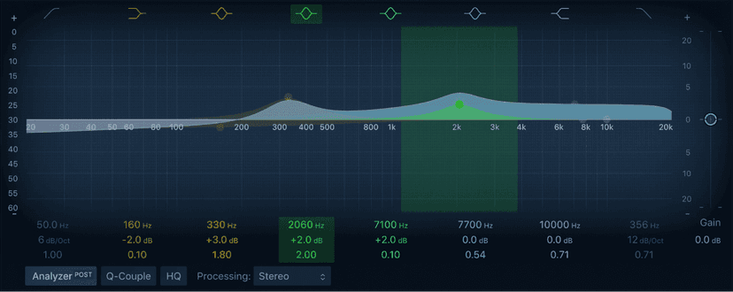
Channel EQ graphic display
The graphic display shows the current curve of each EQ band. The scale is shown in decibels. The color of each band matches the corresponding button above the display. Each colored band (and corresponding Frequency, Gain, and Q field) is highlighted as you move the pointer across it. Click a curve line segment, the (center frequency) control point, or anywhere in the colored space between the zero line and EQ curve to adjust the band.
Click the control point to select a band for editing. Once a band is selected, no other band control point that falls within the active (colored) area of the selected band can be selected.
Click the graphic display background (outside a colored band) to deselect the selected band.
Hold down Command while performing any of the following operations to limit dragging to vertical or horizontal movement.
- Drag anywhere in the colored band to adjust gain and the center frequency.
- Drag the vertical lines that encompass the selected band to adjust the Q (bandwidth) only. Two arrow icons are shown.
- Use a two-finger vertical swipe with the trackpad, or a single-finger vertical swipe with the Magic Mouse, to adjust the Q value of the selected band.
- Drag the horizontal line in the selected band to adjust the gain only. If Q-Coupling is enabled, both the gain and bandwidth are adjusted. Two arrow icons are shown.
- Drag the intersection of vertical and horizontal lines in the selected band to adjust the gain and Q simultaneously. Four arrow icons are shown.
- Drag the control point to adjust the center frequency only.Note: Horizontally dragging the control point in band 1 and band 8 adjusts both the frequency and Q.
- Hold down Option-Command to adjust the Q and center frequency simultaneously. A “Q” icon is shown at the pointer position.
Linear Phase EQ
The high-quality Linear Phase EQ effect is similar to Channel EQ, sharing the same parameters and eight-band layout. You can copy settings between them. If you replace Channel EQ with Linear Phase EQ (or vice versa) in the same effect slot, the current settings are automatically transferred to the new EQ.
Linear Phase EQ uses a different underlying technology to Channel EQ that preserves the phase of the audio signal. Phase coherency is always maintained, even when you apply extreme EQ curves to the sharpest signal transients. This differs from Channel EQ, which can introduce phase shifts of the signal that can have an audible (and often desirable) effect on the sound.
A further difference between Channel EQ and Linear Phase EQ is that the latter uses a fixed amount of CPU resources, regardless of the number of active bands. Linear Phase EQ also introduces greater amounts of latency.
Note: Use the Linear Phase EQ where phase coherence between tracks is needed, such as multi microphone recordings. The Linear Phase does not introduce any phase shift to the signal which can also be beneficial in mastering, but it does impact on the onset of the transient. This is most evident when using steep cut filters, or high boosts/cuts of narrow filter bands.
Vintage EQ collection
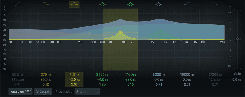
The Logic Pro Vintage Console EQ, Logic Pro Vintage Graphic EQ, and Logic Pro Vintage Tube EQ plug-ins are modeled on the original EQ circuits of three classic units from the 1950s, 1960s, and 1970s.
The unique output stage of each unit is also modeled, allowing you to pair the output stage of any unit with the original or other EQ models.
Further enhancements include fully sweepable frequency controls that allow more detailed signal contouring than the fixed frequency options found on some of the original devices.
Each vintage EQ unit provides a distinct tonal signature that imparts a sonic color on signals, unlike precise, clean modern equalizers such as the other Logic EQs.
All vintage EQ models share a set of common Output parameters, along with unique parameters that are discussed in each section.
Output parameters
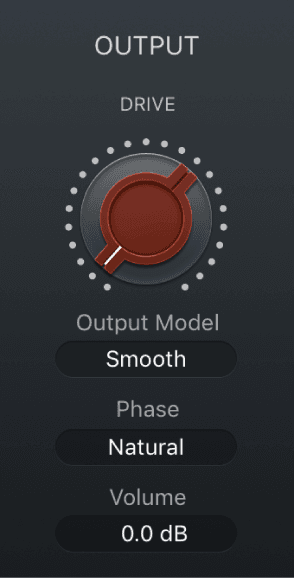
- Drive knob: Set the amount of gain/saturation of the chosen vintage EQ output stage. This imparts the distortion and coloration of the original hardware output stage, even if all EQ bands are in a neutral position.
- Output Model pop-up menu: Choose a vintage EQ model output stage. You can use the matching output stage model for the active EQ or can choose the output stage of another unit. The output stage allows you to add harmonic distortion to your signals.
- Silky (Tube EQ): The output stage of the Logic Pro Vintage Tube EQ.
- Punchy (Graphic EQ): The output stage of the Logic Pro Vintage Graphic EQ.
- Smooth (Console EQ): The output stage of the Logic Pro Vintage Console EQ.
- Phase pop-up menu: Set the processing mode of the EQ and the chosen output stage. Natural mirrors the cut/boost phase shifts of the original EQ. Linear allows EQ changes without phase shifts of the source signal.Each analog EQ introduces phase shifts of the signal which can have an audible (and often desirable) effect on the sound. In some situations, however, phase shifts can affect transients. This is especially the case when using steep cut filters, or high boost of narrow filters. Linear phase filters let you change only the gain of a certain frequency area of your material by retaining the phase, with slightly higher latency than in natural mode.
- Volume field: Drag vertically to set the overall plug-in output level. Range is ±25 dB.
Vintage Console EQ
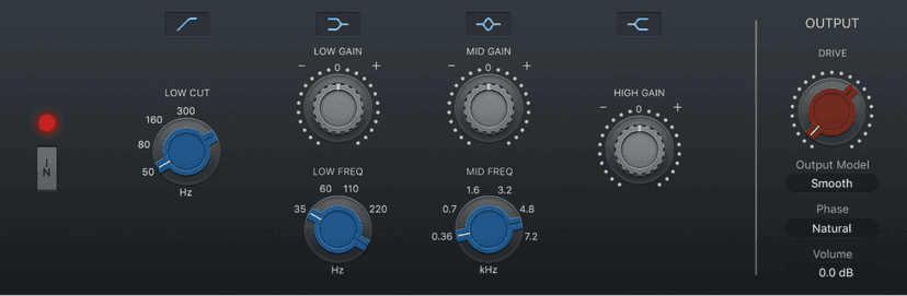
Vintage Console EQ emulates the EQ section of a well-known mixing console channel that is noted for its tonal color, warmth, smooth top end, and mid-forward presence. A three-band design with switchable low and mid range bands and a fixed 12 kHz high frequency band, it also has a passive third-order (18 dB/octave) low cut/highpass filter.
The original console module is regarded as a cult classic by many recording engineers, and has been used on countless hit records over the past 40 to 50 years.
Vintage Graphic EQ
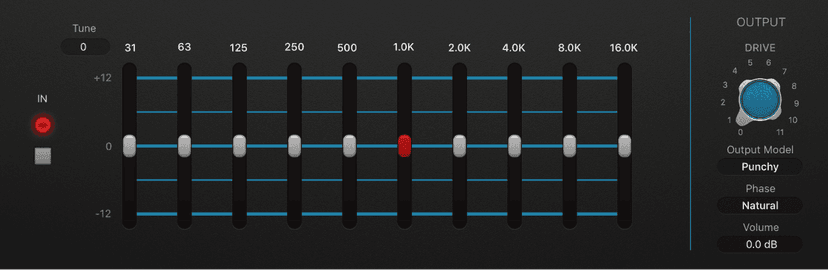
Vintage Graphic EQ is based on a classic mixing console module. The 10 EQ bands provide 12 dB of cut/boost. It emulates the Proportional Qdesign of the original device, which widens filter bandwidth at lower cut/boost levels and narrows filter bandwidth at higher cut/boost levels.
Frequencies aren’t fixed at the default values, and you can proportionally scale all bands to provide more focus on a portion of the overall frequency spectrum. This flexibility makes it great for precise signal shaping and also a useful tool for tasks such as tuning difficult rooms.
Vintage Tube EQ
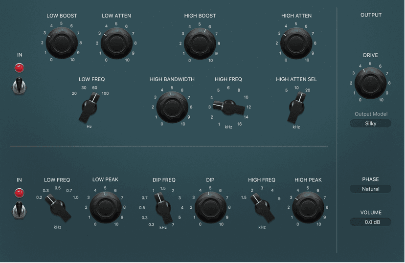
Vintage Tube EQ emulates two retro EQ units that were often paired as they complemented each other. These units are still in use today, despite being out of production for decades.
The main original unit (upper) that Vintage Tube EQ is based on is a valve-equipped analog design. It is a lossless passive equalizer. This means that the signal level remains constant even if the EQ is switched out. The original unit is noted for the “musical” quality of its filters, making it a versatile tool for mixing and mastering.
The low-frequency section of Vintage Tube EQ is a shelving EQ with sweepable frequency bands between 20 and 100 Hz. These frequencies can be boosted by 13.5 dB or cut by 17.5 dB. You can create unusual EQ curves by simultaneously boosting and cutting overlapping frequencies.
The Vintage Tube EQ high-frequency section provides up to 18 dB of boost at frequencies sweepable from 3 to 16 kHz. A Bandwidth control changes the Q value. A shelf-cut EQ provides up to 16 dB of attenuation between 5 and 20 kHz.
The second emulated EQ model (lower) is often paired with the original unit. It’s the perfect partner for the upper unit, adding mid-range flexibility that lets you fine-tune signals in this frequency spectrum, with a beautifully matched tonal signature.
Pitch effects
You can use the pitch effects to transpose or correct the pitch of audio signals. These effects can also be used for creating unison or slightly thickened parts, or even for creating harmony voices.
You can also define a scale to automatically correct some, but not all, sung notes in a vocal performance, for example. This enables you to effectively perfect an imperfect vocal take.
You can also use pitch correction effects creatively, modifying all pitched notes in a performance to a single pitch or a particular key.
Pitch Correction effect
You can use the Pitch Correction effect to fix the pitch of incoming audio signals. Improper intonation is a common problem with vocal tracks, for example. The sonic artifacts that can be introduced by the process are minimal and are almost silent when making moderate corrections. This is kind of like automatic flex pitch, or more commonly referred to as Atuo Tune.
Pitch correction works by accelerating and slowing down the audio playback speed, matching the input signal (sung vocal) with the correct note pitch. If you try to correct larger intervals, you can create special effects. Natural articulations of the performance, such as breath noises, are preserved.
Any scale can be defined as a pitch reference (technically speaking, this is known as a pitch quantization grid). Improperly intonated notes are corrected in accordance with this scale.
The Pitch Correction effect can be fully automated. This means that you can automate the Scale and Root parameters to follow harmonies in the project. Depending on the accuracy of the original intonation, setting the appropriate key with the Scale parameter may suffice. Less precise intonations may need more significant changes to the Scale and Root parameters.
Note: Polyphonic recordings, such as choirs, and highly percussive signals with prominent noisy portions cannot be corrected to a specific pitch. Despite this, you may want to try the plug-in on some drum sounds, such as toms and congas because it can deliver interesting results.
Pitch Correction parameters
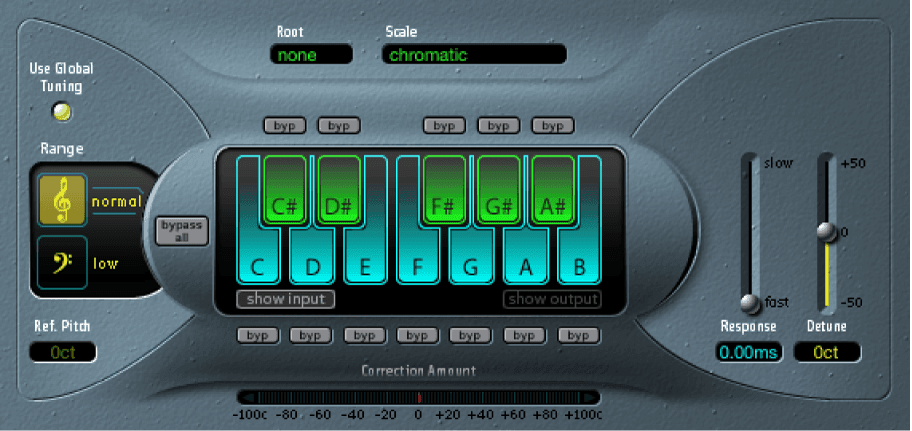
- Use Global Tuning button: Turn on to use project Tuning settings for the pitch correction process. Turn off to set the reference tuning with Ref. Pitch.
- Normal and low buttons: Set the pitch range that is scanned (for notes that need correction).
- Ref. Pitch field: Set the reference tuning in cents (relative to the root).
- Root pop-up menu: Choose the root note of the scale.
- Scale pop-up menu: Choose a pitch quantization grid.
- Keyboard: Click a key to exclude the corresponding note from pitch quantization grids. This effectively removes this key from the scale, resulting in note corrections that are forced to the nearest available pitch (key).
- Bypass buttons: Exclude the corresponding note from pitch correction. In other words, all notes that match this pitch are not corrected. This applies to both user and built-in scale quantization grids.
- Bypass All button: Quickly compare the corrected and original signals or audition automation changes.
- Show input and show output buttons: Show the pitch of the input or output signal, respectively, on the notes of the keyboard.
- Correction Amount display: Indicates the amount of pitch change. The red marker indicates the average correction amount over a longer time period. You can use the display when discussing (and optimizing) the vocal intonation with a singer during a recording session.
- Response slider and field: Determine how quickly the voice reaches the corrected destination pitch.Singers use portamenti and other gliding techniques. If you choose a Response value that’s too high, seamless portamenti turn into semitone-stepped glissandi, but the intonation is perfect. If the Response value is too low, the pitch of the output signal won’t change quickly enough. The optimum setting for this parameter depends on the singing style, tempo, vibrato, and accuracy of the original performance.
- Detune slider and field: Detune the output signal by the set value.
Pitch Shifter
Pitch Shifter provides a simple way to combine a pitch-shifted version of the signal with the original signal.
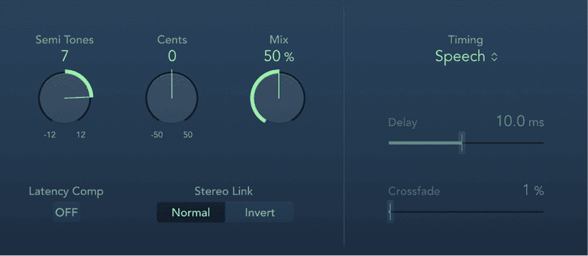
Pitch Shifter parameters
- Semi Tones knob and field: Set the pitch shift value in semitones.
- Cents knob and field: Control detuning of the pitch shift value in cents (1/100th of a semitone).
- Mix knob and field: Set the balance between the effect and original signals.
- Latency Comp button: Turn on to compensate for delays that may be introduced by some algorithms with particular types of source material.
- Stereo Link buttons: Normal retains the source stereo signals. Invert swaps (inverts) stereo channel signals, with right channel processing occurring on the left, and vice versa.
- Timing pop-up menu: Choose an algorithm to determine how timing is derived.
- Drums: Maintains the groove (rhythmic feel) of the source signal.
- Speech: Provides a balance between both the rhythmic and harmonic aspects of the signal. This is suitable for complex signals such as spoken-word recordings, rap, and hybrid signals such as rhythm guitar.
- Vocals: Retains the intonation of the source, making it well-suited for signals that are inherently harmonic or melodious, such as string pads.
- Manual: Uses the settings of the Delay, Crossfade, and Stereo Link parameters.
- Pitch Tracking: Follows the pitch of incoming audio material.
Note: The following parameters are active only when Manual is chosen from the Timing pop-up menu.
- Delay slider and field: Set the amount of delay applied to the input signal. The lower the frequencies of the input signal, the higher (longer) a delay time is required—to effectively pitch shift the signal.
- Crossfade slider and field: Set the range (shown as a percentage of the original signal) used to analyze the input signal.
Vocal Transformer
Vocal Transformer can be used to transpose the pitch of a vocal line, to augment or diminish the range of the melody, or even to reduce it to a single note that mirrors the pitches of a melody. No matter how you change the pitches of the melody, the constituent parts of the signal (formants) remain the same.
You can shift the formants independently, which means that you can turn a vocal track into a Mickey Mouse voice, while maintaining the original pitch. Formants are characteristic emphases of certain frequency ranges. They are static and do not change with pitch. Formants are responsible for the specific timbre of a given human voice.
Vocal Transformer is well suited to extreme vocal effects. The best results are achieved with monophonic signals, including monophonic instrument tracks. It is not designed for polyphonic voices—such as a choir on a single track—or other chordal tracks.
Using the Vocal Transformer Pitch and Formant parameters
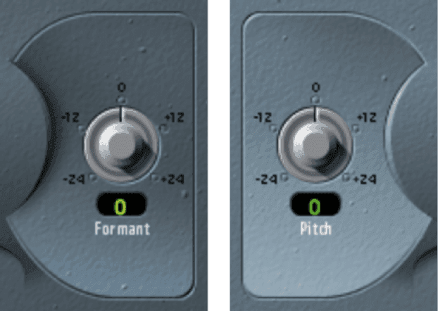
- Rotate the Pitch knob to transpose the pitch of the signal upward or downward. Adjustments are made in semitone steps. Incoming pitches are indicated by a vertical line below the Pitch Base field.Transpositions of a fifth upward (Pitch = +7), a fourth downward (Pitch = −5), or by an octave (Pitch = ±12) are the most useful harmonically.As you alter the Pitch parameter, you might notice that the formants don’t change.The Pitch parameter is expressly used to change the pitch of a voice, not its character. If you set negative Pitch values for a female soprano voice, you can turn it into an alto voice without changing the specific character of the singer’s voice.
- To shift the formants while maintaining—or independently altering—the pitch: Rotate the Formant knob. If you set this parameter to positive values, the singer sounds like Mickey Mouse. By altering the parameter downward, you can achieve vocals reminiscent of Darth Vader.Tip: If you set Pitch to 0 semitones, Mix to 50%, and Formant to +1 (with Robotize turned off), you can effectively place a singer (with a smaller head) next to the original singer. Both will sing with the same voice, in a choir of two. This doubling of voices is quite effective, with levels easily controlled by the Mix parameter.
Using Vocal Transformer Robotize mode
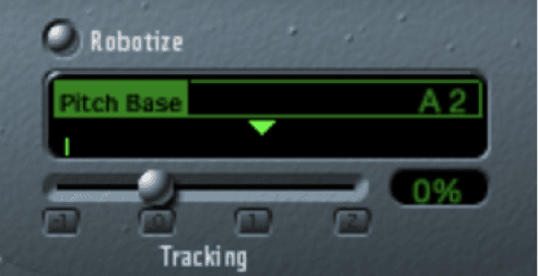
Click the Robotize button to turn on Robotize mode. In this mode, Vocal Transformer can augment or diminish the melody. You can control the intensity of this distortion with the Tracking parameter. Click one of the following buttons to immediately set the Tracking slider to one of these most useful values:
−1 button: Set the slider to −100%. All intervals are mirrored.
0 button: Set the slider to 0%. Delivers interesting results, with every syllable of the vocal track being sung at the same pitch. Low values turn sung lines into spoken language.
1 button: Set the slider to 100%. The range of the melody is maintained. Higher values augment, and lower values diminish, the melody.
2 button: Set the slider to 200%. The intervals are doubled.
The Pitch Base parameter is used to transpose the note that the Tracking parameter is following. For example, with Tracking set to 0%, the pitch of the (spoken) note is transposed to the chosen base pitch value.
Amps and Pedals effects
Logic Pro X features an extensive collection of guitar and bass amplifiers and classic pedal effects. You can play live—or process recorded audio and software instrument parts—through these amps and effects.
The amplifier models recreate vintage and modern tube and solid-state amps. Built-in effect units, such as reverb, tremolo, or vibrato, are also reproduced. The modeled amplifiers can be paired with a number of emulated speaker cabinets. These amplifiers and speaker cabinets can be used as a matching set or combined in other ways to create interesting hybrids.
Also emulated are a number of “classic” foot pedal effects—or stompboxes—that were, and remain, popular with guitarists and keyboardists. As with their real-world counterparts, you can chain pedals in any order to create your sound.
Amp Designer
Amp Designer emulates the sound of more than 20 famous guitar amplifiers and the speaker cabinets used with them. Each preconfigured model combines an amp, a cabinet, and EQ that recreates a well-known guitar amplifier sound. You can process guitar signals directly, reproducing the sound of your guitar played through these amplification systems. You can also use Amp Designer for experimental sound design and processing. You can use it with other instruments as well, applying the sonic character of a guitar amp to a trumpet or vocal part, for example.
The amplifiers, cabinets, and EQs emulated by Amp Designer can be combined in numerous ways to alter the tone. Virtual microphones are used to pick up the signal of the emulated amplifier and cabinet. You can choose from, and position, seven different microphone types. Amp Designer also emulates classic guitar amplifier effects, including spring reverb, vibrato, and tremolo.
The Amp Designer interface is divided into four main parameter sections.
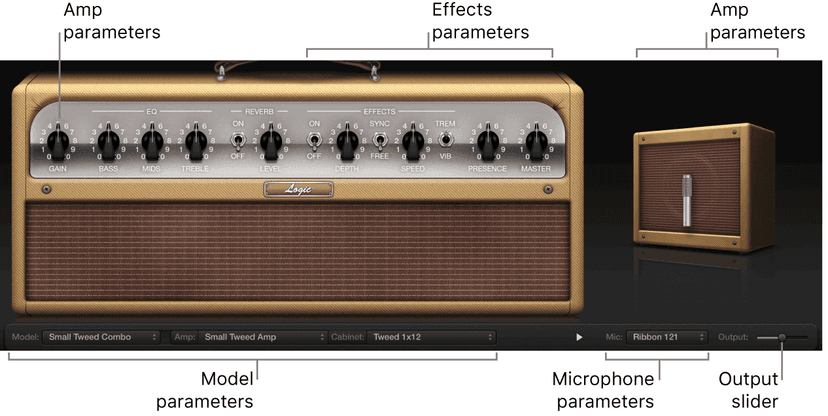
- Model parameters: The Model pop-up menu at the bottom of the window is used to choose a preconfigured model, consisting of an amplifier, a cabinet, an EQ type, and a microphone type. The other pop-up menus enable you to independently choose the type of amplifier, cabinet, and microphone.
- Amp parameters: Located at each end of the knobs section, these parameters are used to set the input gain, presence, and output level of an amp.
- Effects parameters: Located in the center of the knobs section, these parameters control the integrated effects.
- Microphone parameters: Located at the right of the interface, these parameters set the type and position of the microphone that captures the amplifier and cabinet sound.
- Output slider: The Output slider (or the Output field, in the small interface) is found at the lower-right corner of the interface. It serves as the final level control for Amp Designer output that is fed to ensuing Insert slots in the channel strip or directly to the channel strip output.
Amp Designer amplifier controls
The amp parameters include controls for the input gain, presence, and master output. The Gain knob is located to the left in the knobs section, the Presence and Master knobs are to the right, and the Output parameter is at the lower-right edge of the interface.
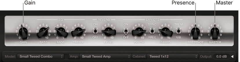
Amplifier parameters
- Gain knob: Set the amount of preamplification applied to the input signal. This control affects specific amp models in different ways. For example, when you use the British Amp, the maximum gain setting produces a powerful crunch sound. When you use the Vintage British Head or Modern British Head, the same gain setting produces heavy distortion, suitable for lead solos.
- Presence knob: Adjust the ultra-high frequency range—above the range of the Treble control. The Presence parameter affects only the output (Master) stage.
- Master knob: Set the output volume of the amplifier signal sent to the cabinet. For tube amplifiers, increasing the Master level typically produces a compressed and saturated sound, resulting in a more distorted and louder signal.WARNING: Because high Master knob settings can produce an extremely loud output that can damage your speakers or hearing, start with a low Master knob setting and then slowly increase it.
- Output slider or field: Set the final output level of Amp Designer.Note: The slider is replaced with a field in the small interface.
Amp Designer microphone parameters
Amp Designer provides seven virtual microphone types. As with other components in the tone chain, different selections can yield very different results. After choosing a cabinet, you can set the type of microphone to emulate and can place the microphone, relative to the cabinet.
The Mic pop-up menu is near the lower right. The speaker-adjustment graphic appears when you move your pointer in the area above the Mic pop-up menu.
Note: The parameters described in this section are accessible only in the full Amp Designer interface. If you are in the small interface, click the disclosure triangle to the right of the Output field to switch to the full interface.
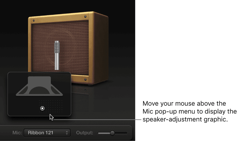
Microphone parameters
- Microphone XY pad: Microphone position is indicated by the white dot in the XY pad. Drag the dot to change microphone position and distance. Placement is relative to the cabinet and is limited to near-field positioning.By default, the microphone is placed in the center of the speaker cone (on-axis). This placement produces a fuller, more powerful sound, suitable for blues or jazz guitar tones. If you place the microphone on the rim of the speaker (off-axis), you obtain a brighter, thinner tone, making it suitable for cutting rock or R & B guitar parts. Moving the microphone closer to the speaker emphasizes bass response.
- Mic pop-up menu: Choose a microphone model.
- Condenser models: Emulates the sound of high-end studio condenser microphones. The sound of condenser microphones is fine, transparent, and well-balanced. Choose from: Condenser 87 and Condenser 414.
- Dynamic models: Emulates the sound of popular dynamic cardioid microphones. Dynamic microphones sound brighter and more cutting than Condenser models. The mid-range is boosted, with softer lower-mid frequencies, making dynamic microphones a good choice for rock guitar tones; useful if you want guitars to cut through other tracks in a mix. Choose from: Dynamic 20, Dynamic 57, Dynamic 421, and Dynamic 609.
- Ribbon 121: Emulates the sound of a ribbon microphone. A ribbon microphone is a type of dynamic microphone that captures a sound often described as bright or brittle, yet still warm. It is useful for rock, crunch, and clean tones.
Tip: Combining multiple microphone types can produce an interesting sound. Duplicate the guitar track, and insert Amp Designer on both tracks. Select different microphones in each Amp Designer instance while retaining identical settings for all other parameters, then set track signal levels
Bass Amp Designer
Bass Amp Designer emulates the sound of three famous bass guitar amplifiers and the speaker cabinets used with them. Each preconfigured model combines an amp and cabinet that recreates a well-known bass guitar amplifier sound. The amp and cabinet can be combined with integrated compression and EQ units to alter the tone. You can process signals directly, reproducing the sound of your bass played through these amplification systems. Virtual microphones are used to pick up the signal of the emulated amplifier and cabinet. You can choose from, and position, three different microphone types.
When recording, many bass players use a direct connection to a mixing board or other recording equipment, often using a passive (non powered) or active (powered) D.I. box (Direct Injection box). The use of a pre-amp with passive or active EQ and a hardware compressor instead of, or in addition to, a D.I. box is extremely popular too. Bass Amp Designer emulates a professional-level American D.I. box.
Bass Amp Designer has a two channel design—one for the pre-amp and one for the D.I. box. This lets you flexibly change the signal flow for the following playing and recording configurations: pre-amp with passive or active EQ, compressor, a straight power amp, just the sound of the cabinets and microphones, D.I. box alone, bass amp alone, or both in parallel.
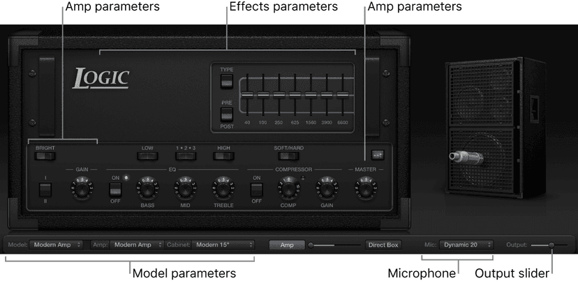
The Bass Amp Designer interface is divided into four main parameter sections.
- Model parameters: The Model pop-up menu at the lower left of the window is used to choose a preconfigured model, consisting of an amplifier, a cabinet, and a microphone type. The other pop-up menus enable you to independently choose the type of amplifier, cabinet, and microphone.
- Amp parameters: Located at each end of the knobs section, these parameters are used to set the input gain, presence, and output level of the amp.
- Effects parameters: Located in the center of the knobs section, these parameters control the integrated EQ and compressor effects. A further graphic or parametric EQ is shown above the compressor controls when the EQ button is turned on.
- Microphone parameters: Located at the right of the interface, these parameters set the type and position of the microphone that captures the amplifier and cabinet sound.
- Output slider: The Output slider is found at the lower-right corner of the interface. It serves as the final level control for Bass Amp Designer output that is fed to ensuing Insert slots in the channel strip, or directly to the channel strip output.Note: This parameter is different from the Master control, which serves the dual purpose of sound design as well as controlling the level of the Amp section.
Pedalboard effects
Pedalboard simulates the sound of a number of famous “stompbox” pedal effects. You can process any audio signal with a combination of stompboxes.
You can add, remove, and reorder pedals. The signal flow runs from left to right in the Pedal area. The addition of two discrete busses, coupled with splitter and mixer units, lets you experiment with sound design and precisely control the signal at any point in the signal chain.
All stompbox knobs, switches, and sliders can be automated. Eight Macro controls enable real-time changes to any pedal parameter with a MIDI controller.
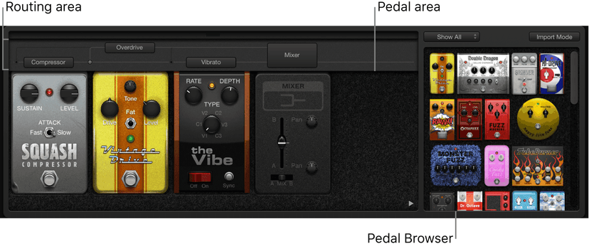
- Pedal Browser: Shows all pedal effects and utilities. These can be dragged into the Pedal area as part of the signal chain. This interface area is also used for the alternative import mode.
- Pedal area: This is where you determine the order of effects and set effect parameters. You can add, replace, and remove stompboxes here.
- Router: Used to control signal flow in the two effects busses (Bus A and Bus B) available in Pedalboard.
- Macro Controls: Used to assign eight MIDI controllers, which can be used to control any stompbox parameter in real time.
Pedalboard Browser
Pedalboard offers dozens of pedal effects and utilities in the Pedal Browser on the right side of the interface. Each effect and utility is grouped into a category, such as distortion, modulation, and so on.
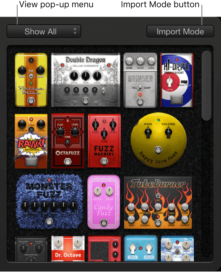
- View pop-up menu: Choose a pedal category.
- Pedal Browser: Shows only the stompboxes within the category you choose in the View pop-up menu.
The effect and utility pedals are broken up into the following sections:
- Distortion pedals
- Pitch pedals
- Modulation pedals
- Delay pedals
- Filter pedals
- Dynamics pedals
- Utility pedals
Specialized effects
Logic includes a couple of specialized effects designed to address tasks encountered during production or performance.
Exciter
Exciter generates high frequency components that are not part of the original signal. It does this by utilizing a nonlinear distortion process that resembles the one used to produce overdrive and distortion effects.
Unlike this process, however, the Exciter distortion process involves passing the input signal through a highpass filter before feeding it into the harmonics (distortion) generator. Artificial harmonics are thus added to the original signal, and these added harmonics contain frequencies at least one octave above the threshold of the highpass filter. The distorted signal is then mixed with the original, dry signal.
You can use Exciter to add life to recordings, particularly audio tracks with a weak treble frequency range. You can also use Exciter to enhance guitar tracks.
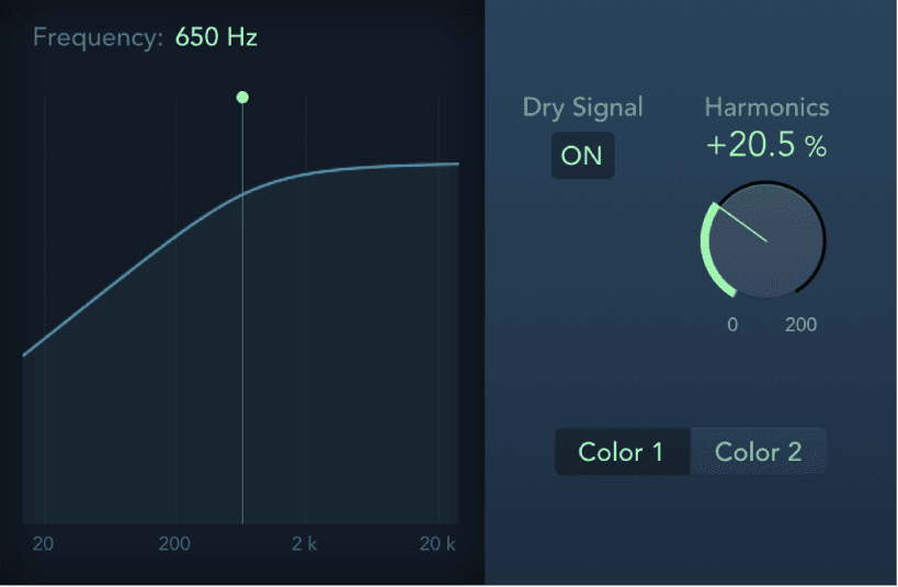
Exciter parameters
- Frequency field: Drag vertically to set the cutoff frequency of the highpass filter. The input signal passes through the filter before (harmonic) distortion is introduced.
- Frequency display: Shows the frequency range used as the source signal for the excite process. You can drag the green line or handle to set the cutoff frequency.
- Dry Signal button: Turn on to mix the original (pre-effect) signal with the effect signal. Turn off to hear only the effect signal.
- Harmonics knob and field: Set the ratio between the effect and the original signals. If the Dry Signal button is turned off, this parameter has no effect.Note: In most cases, it is preferable to select higher Frequency and Harmonics values, because human ears cannot easily distinguish between the artificial and original high frequencies.
- Color 1 and 2 buttons: Turn on Color 1 to generate a less dense harmonic distortion spectrum. Color 2 generates more intense harmonic distortion.Note: Color 2 also introduces more intermodulation distortions, which can result in unpleasant artifacts.
SubBass
SubBass generates frequencies below those of the original signal, resulting in artificial bass content. The simplest use for SubBass is as an octave divider, similar to octaver effect pedals for electric bass guitars. Whereas such pedals can only process a monophonic input sound source of clearly defined pitch, SubBass can be used with complex summed signals as well.
SubBass creates two bass signals, derived from two separate portions of the incoming signal. These are defined with the High and Low parameters.
WARNING: Using SubBass can produce extremely loud output signals. Choose moderate monitoring levels, and only use loudspeakers that are actually capable of reproducing the very low frequencies produced. Never try to force a loudspeaker to output these frequency bands with an EQ.
SubBass parameters
SubBass provides the following parameters.
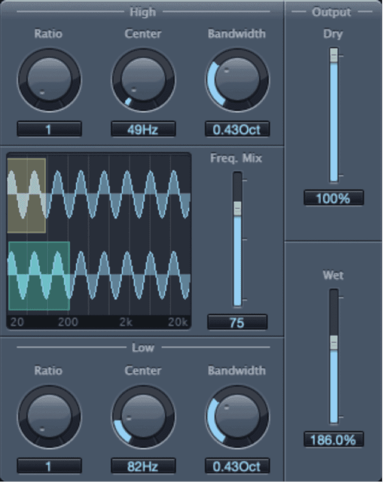
SubBass parameters
- High Ratio knob and field: Adjust the ratio between the generated signal and the upper frequency band of the original signal.
- High Center knob and field: Set the center frequency of the upper frequency band.
- High Bandwidth knob and field: Set the width of the upper frequency band.
- Graphic display: Shows the selected upper and lower frequency bands.
- Freq. Mix slider and field: Adjust the mix ratio between the upper and lower frequency bands.
- Low Ratio knob and field: Adjust the ratio between the generated signal and the lower frequency band of the original signal.
- Low Center knob and field: Set the center frequency of the lower frequency band.
- Low Bandwidth knob and field: Set the width of the lower frequency band.
- Dry slider and field: Set the amount of dry (non-effect, original) signal.
- Wet slider and field: Set the amount of wet (effect) signal.
Do this now
- Put ChromaVerb on a snare and find a room, not an effect.
- Swap it for Space Designer with a real impulse response and compare.
- Then EQ the reverb return - high-pass it at 300 Hz - and listen to the mix get bigger and cleaner at the same time.
Almost every reverb problem is solved by filtering the return rather than turning it down.