Audio FX 2
We already took a look at some audio effects that can help you get into the world of processing your sounds in order to get them sounding better, from a sonic standpoint. It's a good thing to start diving a little deeper into exploring some of the options you have and this is where you would probably start drilling into some of the audio effects categories in the selection menu. Let's look at a few more here...
Don't forget... the way to add an Audio effect is
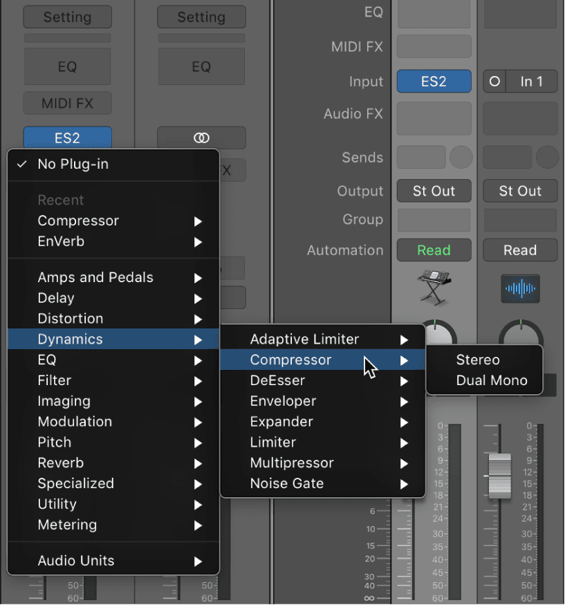
- Click an Audio Effect slot, then choose a plug-in from the pop-up menu.The last visible empty Audio Effect slot in a channel strip is shown at half its height; use it in the same way.
Delays
Delay effects store the input signal—and hold it for a short time—before sending it to the effect input or output.
The delayed signal creates a repeating echo effect after a given time period. Each subsequent repeat is a little quieter than the previous one. Most delays also let you feed a percentage of the delayed signal back to the input. This can result in a subtle, chorus-like effect or cascading, chaotic audio output.
The delay time can often be synchronized to the project tempo by matching the grid resolution of the project, usually in note values or milliseconds.
You can use delays to double individual sounds to resemble a group of instruments playing the same melody, to create echo effects, to place the sound in a large “space,” to generate rhythmic effects, or to enhance the stereo position of tracks in a mix.
Delay effects are generally used as channel insert or bussed effects. They are rarely used on an overall mix (in an output channel), unless you’re trying to achieve an unusual effect.
Echo
This simple echo effect always synchronizes the delay time to the project tempo, enabling you to quickly create echo effects that run in time with your composition.
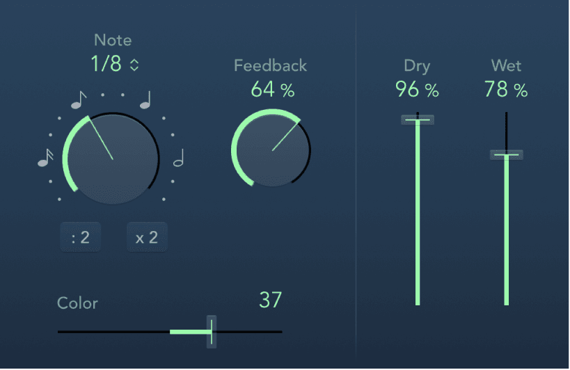
Echo parameters
- Note pop-up menu and knob: Choose the grid resolution of the delay time in musical note durations, based on the project tempo. Notes (and dots) are displayed around the Note knob when synchronized with the project tempo. Click these buttons or dots (or rotate the knob) to choose an exact synchronization value.
- : 2 and x 2 buttons: Halve or double the current delay time.
- Feedback knob and field: Determine how often the delay effect is repeated.
- Color slider and field: Set the harmonic content (color) of the delay signal.
- Dry and Wet sliders and fields: Set the amount of original and effect signal.
Delay Designer
Delay Designer is a multitap delay. Unlike traditional delay units that offer only one or two delays (or taps) that may or may not be fed back into the circuit, Delay Designer provides up to 26 individual taps. These taps are all fed from the source signal and can be edited to create unique delay effects.
Delay Designer provides control over the level, pan position, and pitch of each tap. Each tap can also be lowpass or highpass filtered.
Further effect-wide parameters include synchronization, quantization, and feedback.
As the name implies, Delay Designer offers significant sound design potential. You can use it for everything from a basic echo effect to an audio pattern sequencer. You can create complex, evolving, moving rhythms by synchronizing the placement of taps. This leads to further musical possibilities when coupled with judicious use of transposition and filtering. Alternatively, you can set up numerous taps as repeats of other taps, much as you would use the feedback control of a simple delay effect, but with individual control over each repeat.
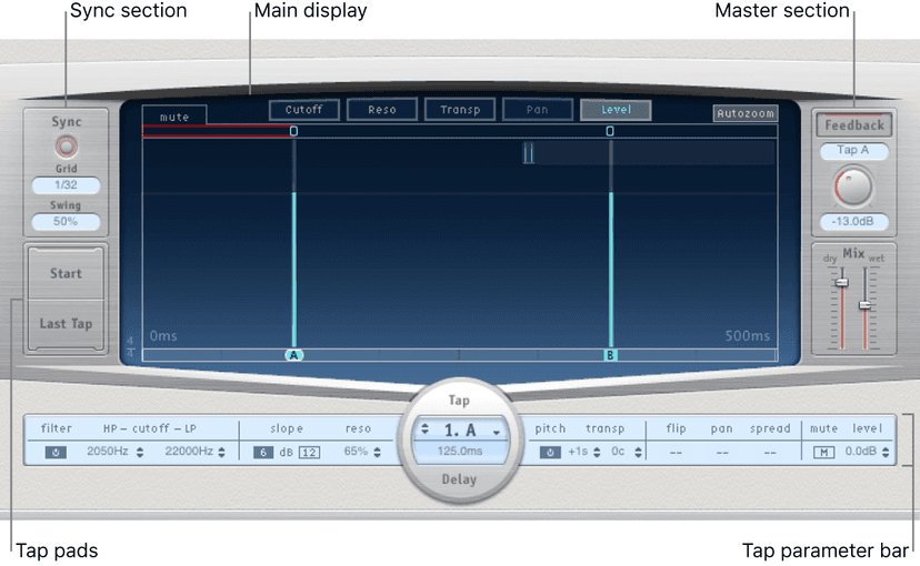
The Delay Designer interface consists of five main sections:
- Main display: Provides a visual representation of all taps. You can see and edit the parameters of each tap in this area.
- Tap parameter bar: Offers a numeric overview of the current parameter settings for the selected tap. You can view and edit the parameters of each tap in this area.
- Tap pads: You can use these two pads to create taps in Delay Designer.
- Sync section: You can set all Delay Designer synchronization and quantization parameters in this area.
- Master section: This area contains the global Mix and Feedback parameters.
The main display is used to view and edit tap parameters. You can choose the parameter to show and can quickly zoom or navigate through all taps.
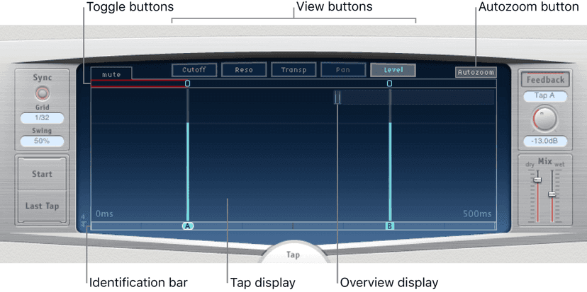
Main display parameters
- View buttons: Click to choose the parameter or parameters shown in the Tap display.
- Autozoom button: Zoom the Tap display out to make all taps visible. Turn Autozoom off if you want to zoom the display in (by dragging vertically in the Overview display) to view specific taps.
- Overview display: Shows all taps in the time range.
- Toggle buttons: Click to turn the parameters of a particular tap on or off. The parameter being toggled is selected with the view buttons. The label at the left of the Toggle bar indicates the parameter.
- Tap display: Represents each tap as a shaded line. Each tap contains a bright bar (or dot for stereo panning) that indicates the value of the parameter. You can directly edit tap parameters in the Tap display area.
- Identification bar: Shows an identification letter for each tap. This also serves as a time position indicator for each tap. You can move taps backward or forward in time along this bar/timeline.
Tap parameter bar
The Tap parameter bar provides access to all parameters of the selected tap. It also shows several parameters that are not available in the Tap display, such as Transpose and Flip.
Editing the parameters of a single, selected tap is fast and precise because all parameters are visible, with no need to switch display views or estimate values with vertical lines. If you choose multiple taps in the Tap display, the values of all selected taps are changed relative to each other.
Option-click a parameter value to reset it to the default setting. If multiple taps are selected, Option-clicking a parameter of any tap resets all selected taps to the default value for that parameter.
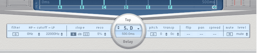
Tap parameter bar controls
- Filter On/Off button: Turn the highpass and lowpass filters on or off (for the selected tap).
- Cutoff HP/LP fields: Set the cutoff frequencies (in Hz) for the highpass and lowpass filters.
- Slope buttons: Determine the steepness of the highpass and lowpass filter slope. Click the 6 dB button for a gentler filter slope, or click the 12 dB button for a steeper, more pronounced filtering effect.Note: You cannot set the slope of the highpass and lowpass filters independently.
- Reso(nance) field: Set the amount of filter resonance for both filters.
- Tap Delay fields: Show the number and name of the selected tap in the upper section and the delay time in the lower section.
- Pitch On/Off button: Turn pitch transposition on or off (for the selected tap).
- Transp(ose) fields: Drag in the left field to transpose pitch by semitones. The right field fine-tunes each semitone step in cents (1/100th of a semitone).
- Flip buttons: Swap the left and right side of the stereo or surround image. Clicking these buttons reverses the tap position from left to right, or vice versa. For example, if a tap is set to 55% left, clicking the flip button swaps it to 55% right.
- Pan field: Set pan position for mono signals, stereo balance for stereo signals, or surround angle when used in surround configurations.
- Pan displays a percentage between 100% (full left) and −100% (full right), which represents the pan position or balance of the tap. A value of 0% represents the center panorama position.
- When used in surround, a surround panner replaces the percentage representation.
- Spread field: Set the width of the stereo spread for the selected tap (in stereo-to-stereo or stereo-to-surround instances).
- Mute button: Mute (silence) or unmute the selected tap.
- Level field: Set the output level for the selected tap.
Creating 'taps'
You can create new delay taps in three different ways: by using the Tap pads, by creating them in the Identification bar, or by copying existing taps.
The fastest way to create multiple taps is to use the Tap pads. If you have a specific rhythm in mind, you might find it easier to tap out your rhythm on dedicated hardware controller buttons, instead of using mouse or trackpad clicks. If you have a MIDI controller, you can assign the Tap pads to buttons on your device.
After a tap has been created, you can adjust its position, or you can remove it.
Taps are assigned letters, based on their order of creation. The first tap to be created is assigned as Tap A, the second tap is assigned as Tap B, and so on. Once assigned, each tap is always identified by the same letter, even when moved in time, and therefore reordered. For example, if you initially create three taps, they are named Tap A, Tap B, and Tap C. If you then change the delay time of Tap B so that it precedes Tap A, it is still called Tap B.
The Identification bar shows the letter of each visible tap. The Tap Delay field of the Tap parameter bar displays the letter of the currently selected tap or the letter of the tap being edited when multiple taps are selected.
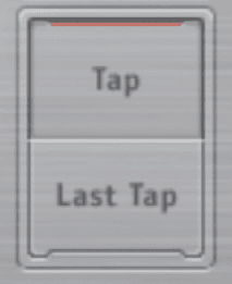
Create taps with the Tap pad
Click the upper pad (Start). Note: Whenever you click the Start pad, it automatically erases all existing taps. Because of this behavior, after you create your initial taps, you will want to create subsequent taps by clicking in the Identification bar.
The upper pad label changes to Tap, and a red tap recording bar appears in the strip below the view buttons. To begin recording new taps, click the Tap button.
To create new taps, click the Tap button. These are created at the exact moments in time of each click, adopting the rhythm of your click pattern.
To finish creating taps, click the Last Tap button. The final tap is added, ending tap recording, and assigning the last tap as the feedback tap.
Note: If you do not click the Last Tap button, tap recording automatically stops after 10 seconds or when the 26th tap is created, whichever comes first.
Create a tap in the Identification bar
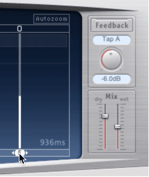
- Click the position where you want to add a tap.
To copy taps in the Identification bar, Option-drag a selection of one or more taps to the position where you want to add the tap or taps. The delay time of copied taps is set to the drag position.
Sample Delay
Sample Delay is more a utility than an effect—you can use it to delay a channel by single sample values.
When used in conjunction with the phase inversion capabilities of the Gain effect, Sample Delay is useful for correcting timing problems that may occur with multichannel microphones. It can also be used creatively to emulate stereo microphone channel separation.
Every sample at a frequency of 44.1 kHz is equivalent to the time taken for a sound wave to travel 7.76 millimeters. If you delay one channel of a stereo microphone by 13 samples, this emulates an acoustic (microphone) separation of 10 centimeters.
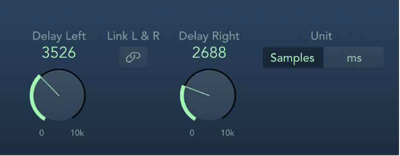
Sample Delay parameters
- Delay knob (L/R) and field: Set the number of samples or milliseconds the incoming signal is delayed by.
- Link L & R button: Turn on to make sure the number of samples is identical for both channels. Adjusting one channel value adjusts the other.
- Unit buttons: Choose Samples or ms to change the appearance and behavior of Delay knob and field values.
Stereo Delay
Stereo Delay lets you set the Delay, Feedback, and Mix parameters separately for the left and right channels. The Crossfeed knob (for each stereo side) sets the feedback intensity level of each signal being routed to the opposite stereo side. You can use Stereo Delay on mono tracks or busses when you want to create independent delays for the two stereo sides.
Note: If you use Stereo Delay on mono channel strips, the track or bus switches to two channel operation from the point of insertion—all Insert slots after the chosen slot are stereo.
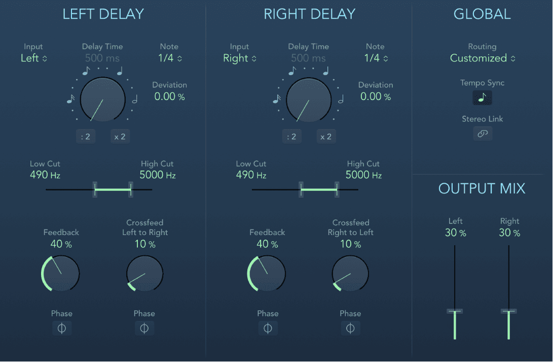
The parameters for the left and right delays are identical. The following descriptions apply to both channels. Global and Output Mix parameters are described after the channel parameters.
Channel parameters
- Input pop-up menu: Choose the input signal for the two stereo sides. Options include Off, Left, Right, L + R, and L − R.
- Delay Time knob and field: Set the delay time in milliseconds or in note values when synchronized with the project tempo. Notes (and dots) are displayed around the Delay Time knob when synchronized with the project tempo. Click these buttons or dots (or rotate the knob) to choose an exact synchronization value.Note: Clicking note or dot values resets the Deviation parameter value. Choose a value from the Note pop-up menu to retain the current Deviation value.
- Note pop-up menu: Set the grid resolution for the delay time when the Tempo Sync button is active.
- Deviation field: Set the amount of deviation from the grid.
- : 2 and x 2 buttons: Halve or double the current delay time.
- Low/High Cut slider and field: Cut frequencies below the Low Cut value and above the High Cut value from the effect signal.
- Feedback knob and field: Set the amount of feedback for the left and right delay signals.
- Feedback Phase button: Invert the phase of the corresponding channel feedback signal.
- Crossfeed Left to Right (Right to Left) knob and field: Transfer the feedback signal of the left channel to the right channel, and vice versa.
- Crossfeed Phase button: Invert the phase of the crossfed feedback signals.
Global and Output Mix parameters
- Routing pop-up menu: Choose the internal signal routing. Options include Customized, Straight, Crossfeed, 90/10, 10/90, Ping Pong L/R, Pan L/R, and Rotate L/R.
- Tempo Sync button: Synchronize delay repeats with the project tempo. Set note values with the Note pop-up menu or Delay Time knob.
- Stereo Link button: Turn on to make corresponding parameter adjustments for both channels. Adjusting one channel value adjusts the other. Relative values are maintained.
- Press Command to temporarily flip stereo linking, allowing you to adjust a control in a linked fashion even when Stereo Link mode is not active.
- Command-drag a slider to adjust a single channel when in Stereo Link mode.
- Note: Stereo Link mode can be automatically disabled when you choose a new routing or setting. Reenable, if required.
- Output Mix sliders and fields: Independently control the level of the left and right channel signals.
Tape Delay
Tape Delay simulates the sound of vintage tape echo machines. It can run at a free rate or can be synchronized with the project tempo. The effect is equipped with a highpass and lowpass filter in the feedback loop, making it easy to create authentic dub echo effects. Tape Delay also includes an LFO for delay time modulation. This can be used to produce chorus effects, even on long delays.
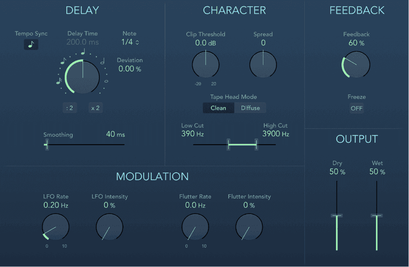
Tape Delay parameters
- Tempo Sync button: Synchronize delay repeats with the project tempo (including tempo changes). The current tempo is shown in the field below the button. Set note values with the Note pop-up menu or Delay Time knob.
- Delay Time knob and field: Set the delay time in milliseconds. Notes (and dots) are displayed around the Delay Time knob when synchronized with the project tempo. Click these buttons or dots (or rotate the knob) to choose an exact synchronization value.Note: Clicking note or dot values resets the Deviation parameter value. Choose a value from the Note pop-up menu to retain the current Deviation value.
- : 2 and x 2 buttons: Halve or double the current delay time.
- Note pop-up menu: Set the grid resolution for the delay time.
- Deviation field: Set the amount of deviation from the grid.
- Smoothing slider and field: Even out the LFO and flutter effect.
- Clip Threshold knob: Set the level of the distorted tape saturation signal. Higher values produce no additional audible distortion. Lower values result in an aggressive distortion. This behavior is influenced by high Feedback values which result in eventual distortion, irrespective of the Clip Threshold value. That said, aggressive distortion and signal breakup are achieved far more rapidly when a low Clip Threshold level is used.
- Spread knob and field: Set the width of the effect signal in stereo instances. This parameter is not available in mono instances.
- Tape Head Mode buttons: Choose Clean or Diffuse mode to emulate a different tape head position. This affects the behavior of other parameters, such as Flutter and Feedback.
- Low/High Cut sliders and fields: Cut frequencies below the Low Cut value and above the High Cut value to shape the sound of taps (delay repeats) with the highpass and lowpass filters. The filters are located in the feedback circuit, which means that the filtering effect increases in intensity with each delay repeat. If you want an increasingly muddy and confused tone, move the High Cut slider toward the left. For ever thinner echoes, move the Low Cut slider toward the right. If you can’t hear the effect, check the Dry and Wet controls and the filter settings.
- LFO Rate knob and field: Set the speed of the LFO.
- LFO Intensity knob and field: Set the amount of LFO modulation. A value of 0 turns off delay modulation.
- Flutter Rate/Intensity knobs and fields: Simulate the speed irregularities of tape transports used in analog tape delay units.
- Flutter Rate: Set the speed variation.
- Flutter Intensity: Set the intensity of the “flutter” effect.
- Feedback knob: Set the amount of delayed and filtered signal that is routed back to the input. Set to the lowest possible value to generate a single echo. Set to 100% to endlessly repeat the signal. The levels of the original signal and taps (echo repeats) tend to accumulate and may cause distortion. Use the Character parameters to change the color of these overdriven signals.
- Freeze button: Capture current delay repeats and sustain them until turned off.
- Dry/Wet sliders and fields: Independently control the amount of original and effect signal.
Distortion effects
Distortion effects simulate the distortion created by vacuum tubes, transistors, or digital circuits.
Vacuum tubes were used in audio amplifiers before the development of digital audio technology. They are still used in musical instrument amplifiers today. When overdriven, tubes produce a musically pleasing distortion that has become a familiar part of the sound of rock and pop music. Analog tube distortion adds a distinctive warmth and bite to the signal.
There are also distortion effects that intentionally cause clipping and digital distortion of the signal. These can be used to modify vocal, music, and other tracks to produce an intense, unnatural tone, or to create sound effects.
Distortion effects include parameters for tone, which let you shape the way the distortion alters the signal (often as a frequency-based filter), and for gain, which let you control how much the distortion alters the output level of the signal.
WARNING: When set to high output levels, distortion effects can damage your hearing—and your speakers. When you adjust effect settings, it is recommended that you lower the output level of the track, and raise the level gradually when you are finished.
Bitcrusher
Bitcrusher is a low-resolution digital distortion effect. You can use it to emulate the sound of early digital audio devices, to create artificial aliasing by dividing the sample rate, or to distort signals until they are unrecognizable.
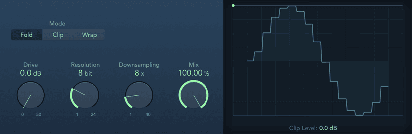
Bitcrusher parameters
- Mode buttons: Set the distortion mode to Fold, Clip, or Wrap. Signal peaks that exceed the clip level are processed.Note: The Clip Level parameter has a significant impact on the behavior of all three modes. This is reflected in the waveform display, so try each mode button and adjust the Clip Level slider to get a feel for how this works.
- Fold button: Set a softer distortion by halving the level of the center portion of the signal above the threshold. The start and end levels of the clipped signal are unchanged.
- Clip button: Enable to cause an abrupt distortion when the clipping threshold is exceeded. Clipping that occurs in most digital systems is closest to Cut mode.
- Wrap button: Set a less severe distortion by offsetting the start, mid, and end levels of the signal above the threshold. This parameter smooths signal levels when they cross the threshold. The center portion of the clipped signal is also softer than in Cut mode.
- Drive knob and field: Set the amount of gain applied to the input signal.Note: Raising the Drive level also tends to increase the amount of clipping at the effect output.
- Resolution knob and field: Set the bit rate (between 1 and 24 bits) to alter the calculation precision of the process. Lower values increase the number of sampling errors, generating more distortion. At extremely low bit rates, the amount of distortion can be greater than the level of the usable signal.
- Downsampling knob and field: Reduce the sample rate. A value of 1x has no effect on the signal, a value of 2x halves the sample rate, and a value of 10x reduces the sample rate to one-tenth of the original. (For example, if you set Downsampling to 10x, a 44.1 kHz signal is sampled at just 4.41 kHz.)Note: Downsampling has no impact on the playback speed or pitch of the signal.
- Mix knob and field: Set the balance between the dry and crushed signal.
- Waveform display: Shows the impact of parameters on the distortion process.
- Clip Level handle and field: Set the point (below the clipping threshold of the channel) at which the signal starts clipping. Drag the green dot at the top left, or the field, to set the clip level.
Clip Distortion
Clip Distortion is a nonlinear distortion effect that produces unpredictable harmonic spectra. It can simulate warm, overdriven tube sounds and can also generate heavy distortions.
Clip Distortion has an unusual combination of serially connected filters. The incoming signal is amplified by the Drive value, passes through a highpass filter, then is subjected to nonlinear distortion. Following the distortion, the signal passes through a lowpass filter. The effect signal is then recombined with the original signal, and this mixed signal is sent through a further lowpass filter. All three filters have a slope of 6 dB/octave.
This unique combination of filters allows for gaps in the frequency spectra that can sound good with this sort of nonlinear distortion.
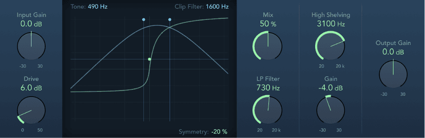
Clip Distortion parameters
- Input Gain knob and field: Set the amount of gain applied to the plug-in input signal. This behaves like a preamplifier for the Drive parameter.
- Drive knob and field: Set the amount of additional gain (distortion) applied to the input signal. After being amplified by Drive, the signal passes through a highpass filter.
- Clip circuit display: Shows the impact of all parameters.
- Tone handle and field: Set the cutoff frequency (in hertz) of the highpass filter.
- Symmetry handle and field: Set the amount of nonlinear (asymmetrical) distortion applied to the signal.
- Clip Filter handle and field: Set the cutoff frequency (in hertz) of the first lowpass filter.
- Mix knob and field: Set the ratio between the effect (wet) signal and original (dry) signals, following the clip filter.
- High Shelving knob and field: Set the frequency (in hertz) of the high shelving filter. If you set the High Shelving Frequency to around 12 kHz, you can use it like the treble control on a mixer channel strip or a stereo hi-fi amplifier. Unlike these types of treble controls, however, you can boost or cut the signal by up to ±30 dB with the Gain parameter.
- LP Filter knob and field: Set the cutoff frequency (in hertz) of the lowpass filter. This processes the mixed signal.
- Gain knob and field: Set the amount of gain applied to the output of signals above the high shelving filter frequency.
- Output Gain knob and field: Set the amount of gain applied to the plug-in output signal.
Distortion
The Distortion effect simulates the low fidelity distortion generated by a bipolar transistor. You can use it to simulate playing a musical instrument through a highly overdriven amplifier or to create unique distorted sounds.
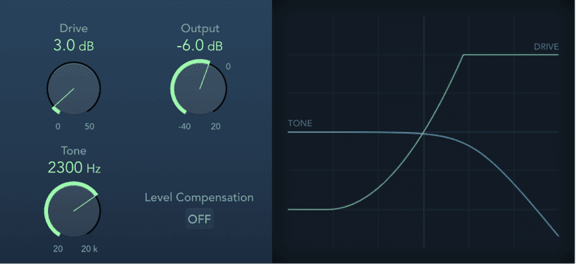
Distortion parameters
- Drive knob and field: Set the amount of saturation applied to the signal.
- Tone knob and field: Set the frequency for the high cut filter. Filtering the harmonically rich distorted signal produces a softer tone.
- Output knob and field: Set the output level.
- Level Compensation button: Turn on to reference the overall processing of the signal to 0 dB. This compensates for increases in loudness caused by adding distortion.
- Display: Shows the impact of parameters on the signal.
Distortion II
Distortion II emulates the distortion circuit of a Hammond B3 organ. You can use it on musical instruments to recreate this classic effect or can use it creatively when designing new sounds.
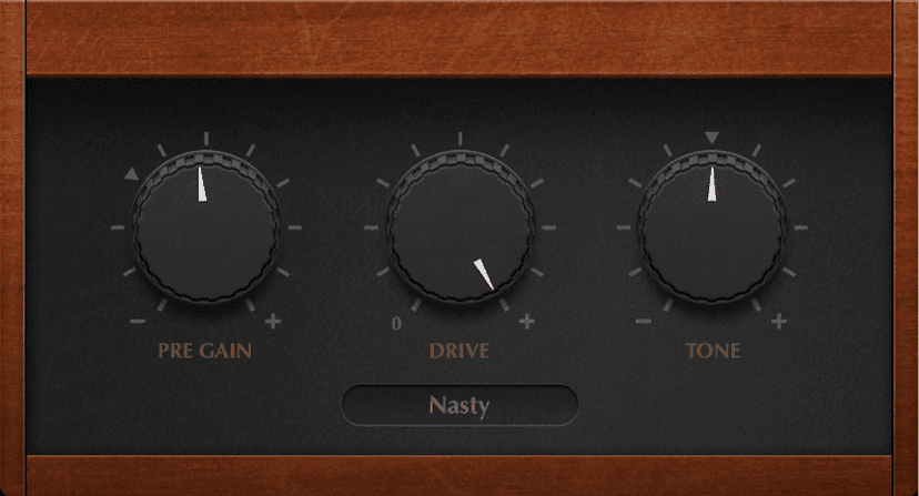
Distortion II parameters
- PreGain knob and field: Set the amount of gain applied to the input signal.
- Drive knob and field: Set the amount of saturation applied to the signal.
- Tone knob and field: Boosts the integrated high shelf filter gain both pre- and post-distortion, which results in a different tone.
- Type pop-up menu: Choose the type of distortion.
- Growl: Emulates a two-stage tube amplifier similar to the type found in a Leslie 122 speaker cabinet, which is often used with the Hammond B3 organ.
- Bity: Emulates the sound of a bluesy (overdriven) guitar amp.
- Nasty: Produces hard distortion, suitable for creating very aggressive sounds.
- Class AB soft: Emulates a softer crossover distortion encountered in transistorized amplifiers when driving a higher load.
- Class AB hard: Emulates a harder crossover distortion encountered in transistorized amplifiers when driving a higher load.Crossover, in this case, refers to a switching between two matched transistors. In Class AB designs, both transistors remain on at all times, reducing the effect of hard switching between them.
Overdrive
Overdrive emulates the distortion produced by a field effect transistor (FET), commonly used in solid-state musical instrument amplifiers and hardware effects devices. When saturated, FETs generate a warmer-sounding distortion than bipolar transistors, such as those emulated by the Logic Pro Distortion effect.
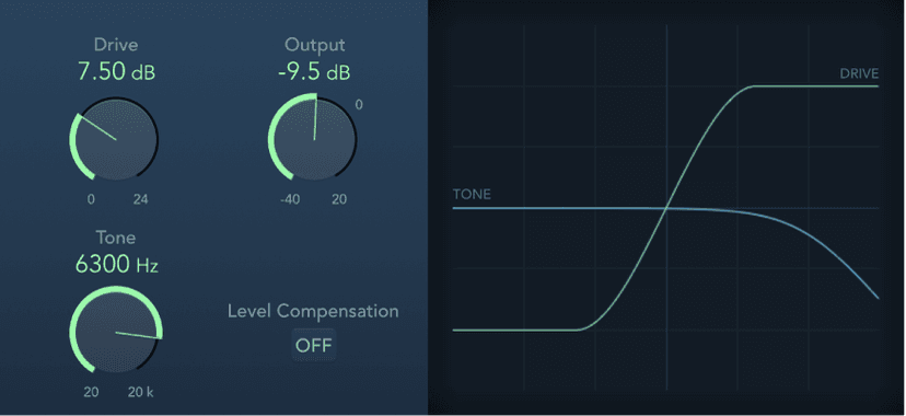
Overdrive parameters
- Drive knob and field: Set the saturation amount for the simulated FET transistor.
- Tone knob and field: Set the frequency of the high cut filter. Filtering the harmonically rich distorted signal produces a softer tone.
- Output knob and field: Set the output level.
- Level Compensation button: Turn on to reference the overall processing of the signal to 0 dB. This compensates for increases in loudness caused by using overdrive.
- Display: Shows the impact of parameters on the signal.
Phase Distortion
The Phase Distortion effect is based on a modulated delay line, similar to a chorus or flanger effect. Unlike these effects, however, the delay time is not modulated by a low frequency oscillator (LFO) but rather by a lowpass-filtered version of the input signal itself, using an internal sidechain. This means that the incoming signal modulates its own phase position.
The input signal only passes the delay line and is not affected by any other process. The Mix parameter blends the effect signal with the original signal.
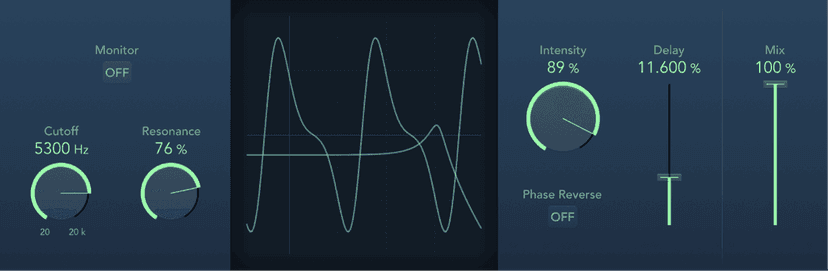
Phase Distortion parameters
- Monitor button: Turn on to hear the input signal in isolation. Turn off to hear the mixed signal.
- Cutoff knob and field: Set the (center) cutoff frequency of the lowpass filter.
- Resonance knob and field: Emphasize frequencies surrounding the cutoff frequency.
- Display: Shows the impact of parameters on the signal.
- Intensity knob and field: Set the amount of modulation applied to the signal.
- Phase Reverse button: Turn on to reduce the delay time on the right channel when input signals that exceed the cutoff frequency are received. Available only for stereo instances of the Phase Distortion effect.
- Delay slider and field: Set the maximum delay time.
- Mix slider and field: Set the percentage of the effect signal mixed with the original signal.
Filter effects
Filters are used to emphasize or suppress frequencies in an audio signal, resulting in a change in the tonal color of the audio.
Logic contains a variety of advanced filter-based effects that you can use to creatively modify your audio. These effects are most often used to radically alter the frequency spectrum of a sound or mix. Several filter effects provide a Side Chain input.
AutoFilter
AutoFilter is a versatile filter effect with several unique features. You can use it to create classic, analog-style synthesizer effects, or as a tool for creative sound design.
The effect works by analyzing incoming signal levels through use of a threshold parameter. Any signal level that exceeds the threshold is used as a trigger for a synthesizer-style ADSR envelope or an LFO (low frequency oscillator). These control sources are used to dynamically modulate the filter cutoff.
AutoFilter lets you choose between different filter types and slopes, control the amount of resonance, add distortion for more aggressive sounds, and mix the original, dry signal with the processed signal.
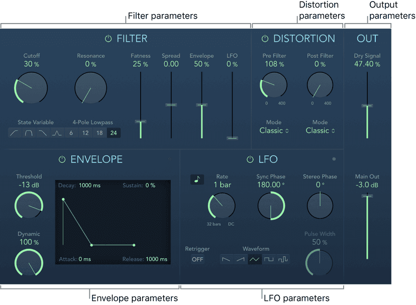
The AutoFilter window is divided into Filter, Envelope, Distortion, LFO, and Output parameter sections.
- Filter parameters: Control the tonal color of the filtered sound.
- Envelope parameters: Define how the filter cutoff frequency is modulated over time.
- Distortion parameters: Distort the signal both before and after the filter.
- LFO parameters: Define how the filter cutoff frequency is modulated by the LFO.
- Output parameters: Set the level of both the dry and effect signal.
Spectral Gate
Spectral Gate is an unusual filter effect that can be used as a tool for creative sound design.
It works by dividing the incoming signal into two frequency ranges—above and below a central frequency band that you specify with the Center Freq and Bandwidth parameters. The signal ranges above and below the defined band can be individually processed with the Low Level and High Level parameters and the Super Energy and Sub Energy parameters.
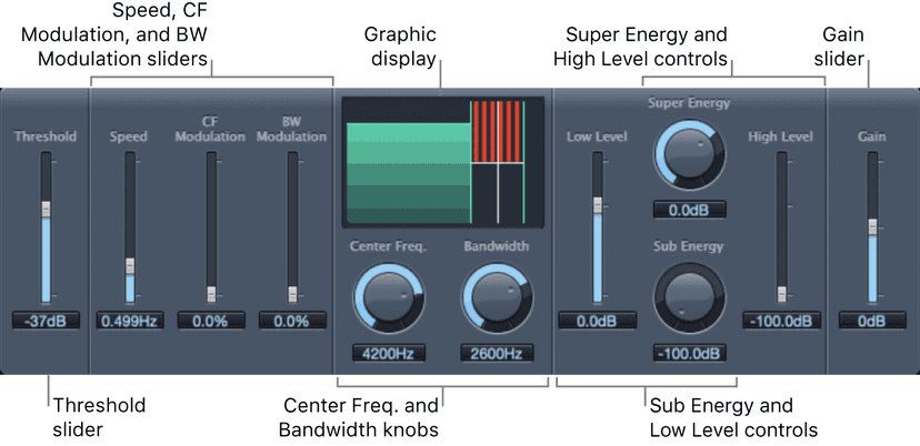
- Threshold slider and field: Set the threshold level that is used to divide frequency ranges. When the threshold is exceeded, the frequency band defined by the Center Freq and Bandwidth parameters is divided into upper and lower frequency ranges.
- Speed slider and field: Set the modulation frequency for the defined frequency band.
- CF Modulation slider and field: Set the intensity of center frequency modulation.
- BW Modulation slider and field: Set the amount of bandwidth modulation.
- Graphic display: Shows the frequency band defined by the Center Freq and Bandwidth parameters.
- Center Frequency knob and field: Set the center frequency of the band you want to process.
- Bandwidth knob and field: Set the width of the frequency band you want to process.
- Super Energy knob and field: Set the level of the frequency range above the threshold.
- High Level slider and field: Mix the frequencies of the original signal—above the selected frequency band—with the processed signal.
- Sub Energy knob and field: Set the level of the frequency range below the threshold.
- Low Level slider and field: Mix the frequencies of the original signal—below the selected frequency band—with the processed signal.
- Gain slider and field: Set the overall output level.
EVOC 20 Filterbank
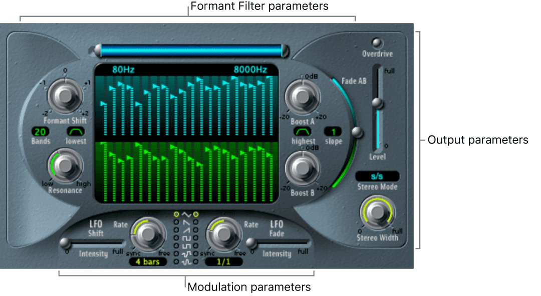
EVOC 20 Filterbank consists of two formant filter banks. The input signal passes through the two filter banks in parallel. Each bank features level faders for up to 20 frequency bands, allowing independent level control of each band. Setting a level fader to its minimum value completely suppresses the formants in that band. You can control the position of the filter bands with the Formant Shift parameter. You can also crossfade between the two filter banks.
The EVOC 20 Filterbank interface is divided into three main sections: the Formant Filter parameters section in the center of the window, the Modulation parameters section at the bottom, and the Output parameters section along the right side.
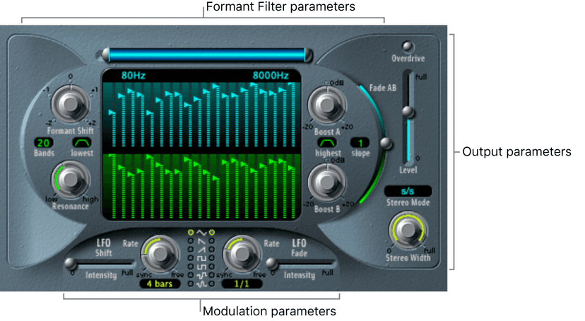
- Formant Filter parameters: Control the frequency bands in the two filter banks—the upper, blue, filter bank A and the lower, green, filter bank B.
- Modulation parameters: Control how Formant Filter parameters are modulated.
- Output parameters: Control the overall output level and panning of the EVOC 20 Filterbank.
A formant is a peak in the frequency spectrum of a sound. In the context of human voices, formants are the key component that enables humans to distinguish between different vowel sounds, based purely on the frequency of these sounds. Formants in human speech and singing are produced by the vocal tract, with most vowel sounds containing four or more formants.
EVOC 20 TrackOscillator
EVOC 20 TrackOscillator is a vocoder with a monophonic pitch tracking oscillator. The tracking oscillator tracks, or follows, the pitch of a monophonic input signal. If the input signal is a sung vocal melody, the individual note pitches are tracked and mirrored, or played, by the synthesis engine.
EVOC 20 TrackOscillator features two formant filter banks, an analysis bank, and a synthesis filter bank. Each offers multiple input options.
You can capture an analysis signal source by using the audio arriving at the input of the channel strip that EVOC 20 TrackOscillator is inserted into or by using a side chained signal from another channel strip.
The synthesis source can be derived from the audio input of the channel strip that EVOC 20 TrackOscillator is inserted into, a side chain signal, or the tracking oscillator.
Because you can select both the analysis and synthesis input signals, EVOC 20 TrackOscillator is not limited to pitch tracking effects; you can also use it for unusual filter effects. For example, you could filter an orchestral recording on one channel strip with train noises side chained from another channel strip. Or you could use it to process drum loops with side chained signals, such as other drum loops or rhythmic guitar, clavinet, and piano parts.
Modulation effects overview
Modulation effects—such as chorus, flanging, tremolo, and phasing—are used to add motion and depth to your sound. Perceived width can be altered with the Logic Pro Spreader effect. Both motion and space can be introduced with the Rotor Cabinet effect.
Modulation effects typically delay the incoming signal by a few milliseconds and use an LFO to modulate the delayed signal. The LFO may also be used to modulate the delay time in some effects.
A low frequency oscillator (LFO) is similar to the sound-generating oscillators in synthesizers, but the frequencies generated by an LFO are so low that they can’t be heard and are therefore used only for modulation purposes. LFO parameters include speed (or frequency) and depth—also called intensity—controls.
You can also control the ratio between the affected (wet) signal and the original (dry) signal. Some modulation effects include feedback parameters, which add part of the effect output back into the effect input.
Other modulation effects involve pitch. The most basic type of pitch modulation effect is vibrato, which uses an LFO to modulate the frequency of the sound. Unlike other pitch modulation effects, vibrato alters only the delayed signal.
More complex modulation effects, such as Ensemble, mix several delayed signals with the original signal. Ringshifter combines a ring modulator with a frequency shifter effect. Logic Pro Modulation Delay allows flanging and chorus effects, emulations of tape speed fluctuations and metallic, robot-like modulations.
Chorus
The Chorus effect delays the original signal, and the delay time is modulated with an LFO. The delayed, modulated signal is then mixed with the original, dry signal.
You can use the Chorus effect to enrich the incoming signal and create the impression that multiple instruments or voices are being played in unison. The slight delay time variations generated by the LFO simulate the subtle pitch and timing differences heard when several musicians or vocalists perform together. Using chorus also adds fullness or richness to the signal, and it can add movement to low or sustained sounds.
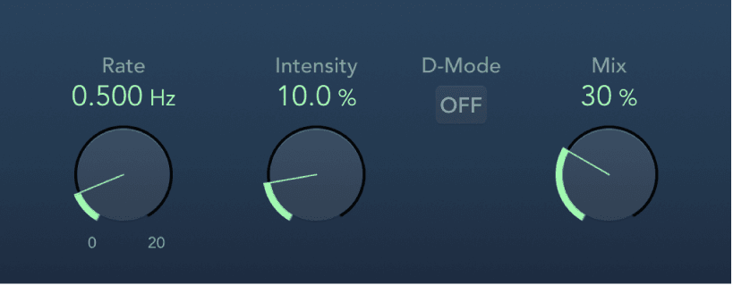
Chorus parameters
- Rate knob and field: Set the frequency, or speed, of the LFO.
- Intensity knob and field: Set the modulation amount.
- D-Mode button: Turn on to introduce a spatial filtering effect that resembles a well-known vintage processor.
- Mix knob and field: Determine the balance between dry and wet signals.
Flanger
The Flanger effect works in much the same way as the Chorus effect but uses a significantly shorter delay time. In addition, the effect signal can be fed back into the input of the delay line.
Flanging is typically used to add a spacey or underwater quality to input signals.
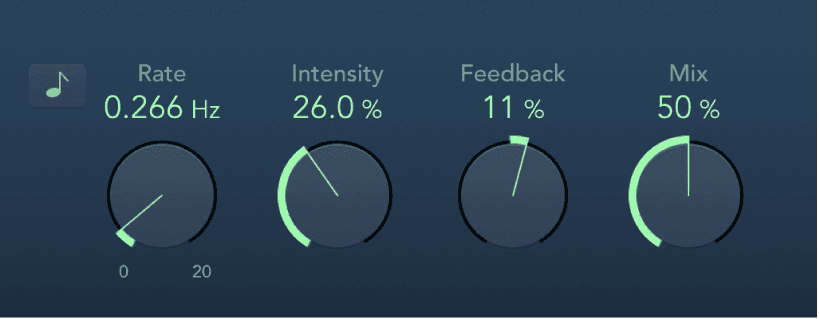
Flanger parameters
- Sync button: Synchronize the modulation speed with the project tempo. Choose musical note values with the Rate knob.
- Rate knob and field: Set the frequency, or speed, of the LFO.
- Intensity knob and field: Set the modulation amount.
- Feedback knob and field: Set the amount of the effect signal that is routed back to the input. This can change the tonal color and can make the sweeping effect more pronounced. Negative Feedback values invert the phase of the routed signal.
- Mix knob and field: Determine the balance between dry and wet signals.
Tremolo
Tremolo modulates the amplitude of the incoming signal, resulting in periodic volume changes. Tremolo is commonly used in vintage guitar combo amps, where it is sometimes incorrectly referred to as vibrato. The graphic waveform display shows all parameters except Rate.
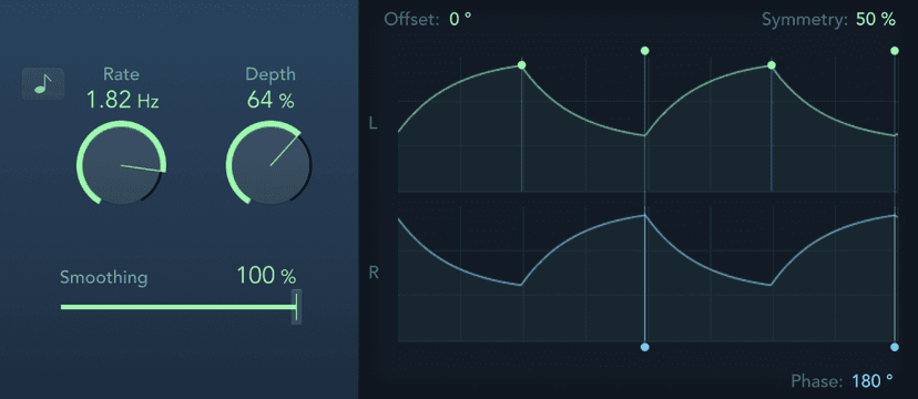
Tremolo parameters
- Sync button: Synchronize the modulation speed with the project tempo. Choose musical note values with the Rate knob.
- Rate knob and field: Set the frequency of the LFO.
- Depth knob and field: Determine the modulation amount.
- Smoothing slider and field: Change the shape of the LFO waveform. Also see Symmetry.
- Distribution pop-up menu: Choose how phase offsets between individual channels are distributed in the surround field. Choose from: circular, left↔right, front↔rear, random, and new random. Available only in surround instances.
- Offset field: Set the amount of left or right movement for the modulation (cycle). This results in small or large tremolo variations.
- Symmetry field: Skew the balance toward the upward or downward phase of waveform cycles.Note: If Symmetry is set to 50% and Smoothing to 0%, the LFO waveform becomes rectangular. The timing of the highest volume signal is then equal to the timing of the lowest volume signal, with the switch between both states occurring abruptly.
- Phase field: Control the phase relationship between individual channel modulations in stereo or surround signals. At 0, modulation values are reached simultaneously for all channels. At values of 180 or −180, there is the greatest possible distance between the modulation phases of the channels.
- Waveform display: Shows and lets you edit modulation Offset, Symmetry, and Phase.
- Modulation is represented by a repeating waveform cycle for each channel. The height represents the LFO intensity, or depth. Adjust the Depth knob to change. Two green handles and two blue handles let you control Offset, Symmetry, and Phase values.
- Offset: Drag the field or the green handle at the left of any waveform cycle to set left or right modulation movement.
- Symmetry: Drag the field or the green handle at the right of any waveform cycle to set the balance between upward or downward waveform phases.
- Phase: Drag the field or either blue handle of any waveform cycle to control phase relationship between channel modulations.
Phaser
The Phaser effect combines the original signal with a copy that is slightly out of phase with the original. This means that the amplitudes of the two signals reach their highest and lowest points at slightly different times. The timing differences between the two signals are modulated by two independent LFOs. In addition, Phaser includes a filter circuit and a built-in envelope follower that tracks volume changes in the input signal, generating a dynamic control signal. This control signal alters the sweep range.
Sonically, phasing is used to create whooshing, sweeping sounds that wander through the frequency spectrum. It is a commonly used guitar effect, but it is suitable for a range of signals.
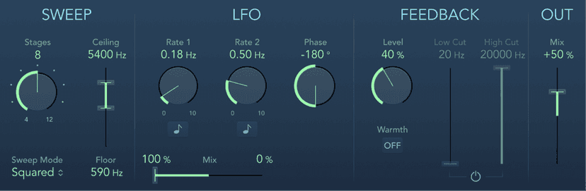
Phaser parameters
- Stages knob and field: Choose phaser algorithms (even numbers) or comb filtering (odd numbers).
- The 4, 6, 8, 10, and 12 settings switch between five different phaser algorithms. All are modeled on analog circuits, with each designed for a specific application.
- The 5, 7, 9, and 11 settings don’t generate actual phasing effects. The more subtle comb filtering effects produced by odd-numbered settings can, however, be useful.
- Sweep Mode pop-up menu: Choose a mode that determines the impact of incoming signal levels on the frequency range. Set the frequency range with the Ceiling and Floor controls.
- Ceiling/Floor sliders and fields: Determine the frequency range affected by LFO modulations. Drag the green slider area between Ceiling and Floor to move the entire range.
- Rate 1/2 knobs and fields: Set the speed for each LFO.
- Sync buttons: Synchronize the modulation speed of each LFO with the project tempo. Choose musical note values with the Rate 1 and Rate 2 knobs.
- Phase knob and field: Control the phase relationship between individual channel modulations. Available only in stereo and surround instances. At 0°, extreme modulation values are achieved simultaneously for all channels. At 180° or −180°, there is the greatest possible distance between channel modulation phases.
- (LFO) Mix slider and fields: Determine the ratio between the two LFOs.
- Distribution pop-up menu: Choose how phase offsets between individual channels are distributed in the surround field. Choose from: circular, left↔right, front↔rear, random, and new random. Available only in surround instances.Note: When you load a setting that uses the “random” option, the saved phase offset value is recalled. If you want to randomize the phase setting again, choose “new random” from the Distribution pop-up menu.
- Level knob and field: Determine the amount of effect signal routed back to the input.
- Warmth button: Enable or disable a distortion circuit, suitable for warm overdrive effects.
- Low/High Cut sliders and fields: Set the cutoff frequency of the lowpass (LP) and highpass (HP) filters.
- Filter button: Enable or disable the filter section.
- (Out) Mix slider and field: Determine the balance of dry and wet signals. Negative values result in a phase-inverted mix of the effect and direct (dry) signal.
Spreader
Spreader widens the stereo spectrum of a signal by periodically shifting the frequency range of the original signal, thus changing the perceived width of the signal. You can also use Spreader to specify the delay between channels in samples, which adds to the perceived width and channel separation of a stereo input signal.
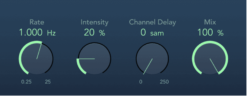
Spreader parameters
- Rate knob and field: Set the speed of the integrated LFO.
- Intensity knob and field: Set the modulation amount.
- Channel Delay knob and field: Set the delay time in samples.
- Mix knob and field: Set the balance between the effect and input signals.
Rotor Cabinet
The Rotor Cabinet effect emulates the rotating loudspeaker cabinet of a Hammond organ. Also known as the Leslie effect, it simulates both the rotating speaker cabinet, with and without deflectors, and the microphones that pick up the sound. You have full control of the Logic Pro Rotor Cabinet effect motor controls and can choose from a range of microphone types.
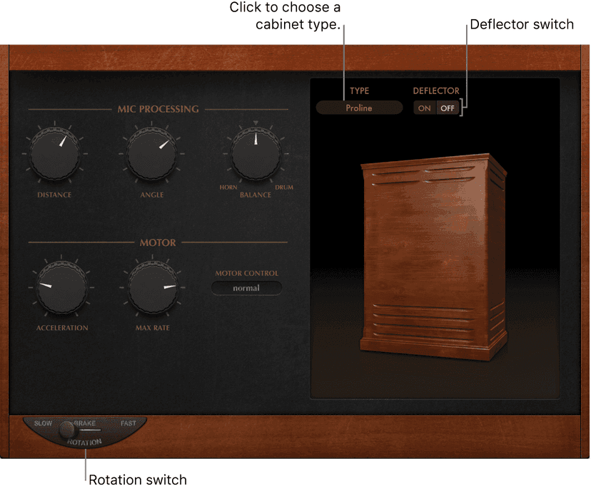
Basic Rotor Cabinet parameters
- Rotation switch: Change the rotor speed between Slow, Brake, or Fast.
- Cabinet Type pop-up menu: Choose a cabinet model.
- Wood: Mimics a Leslie with a wooden enclosure. It sounds like the Leslie 122 or 147 model.
- Proline: Mimics a Leslie with a more open enclosure, similar to a Leslie 760 model.
- Single: Simulates the sound of a Leslie with a single, full-range rotor. It sounds like the Leslie 825 model.
- Split: Routes the bass rotor signal slightly to the left and the treble rotor signal toward the right.
- Wood & Horn IR: Uses an impulse response of a Leslie with a wooden enclosure.
- Proline & Horn IR: Uses an impulse response of a Leslie with a more open enclosure.
- Split & Horn IR: Uses an impulse response of a Leslie with the bass rotor signal routed slightly to the left and the treble rotor signal routed more to the right.
- Deflector switch: Click to emulate a Leslie cabinet with the horn deflectors removed or attached. A Leslie cabinet contains a double horn, with a deflector at the horn mouth. This deflector makes the Leslie sound. You can remove the deflector to increase amplitude modulation and decrease frequency modulation.
Scanner Vibrato
Scanner Vibrato simulates the scanner vibrato section of a Hammond organ. Scanner Vibrato is based on an analog delay line consisting of several lowpass filters. The delay line is scanned by a multipole capacitor that has a rotating pickup. It is a unique effect that cannot be simulated with simple LFOs.
You can choose between three different vibrato and chorus types. The stereo version of the effect features two additional parameters—Stereo Phase and Rate Right. These set the modulation speed independently for the left and right channels.
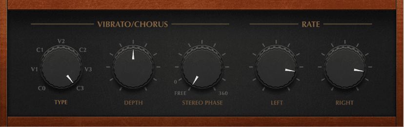
Scanner Vibrato parameters
- Type knob: Choose from three Vibrato positions (V1, V2, and V3) or three Chorus positions (C1, C2, and C3).
- In each of the Vibrato positions, only the delay line signal is heard. Each vibrato type has a different intensity.
- In the three Chorus positions (C1, C2, and C3), the signal of the delay line is mixed with the original signal. Mixing a vibrato signal with an original, statically pitched signal results in a chorus effect. This organ-style chorus sounds different from the Chorus plug-in.
- In the C0 setting, neither the chorus nor the vibrato is enabled.
- Depth knob and field: Set the intensity of the chosen chorus effect type. If a vibrato effect type is chosen, this parameter has no effect.
- Stereo Phase knob and field: Determine the phase relationship between left and right channel modulations. If you set the knob to free, you can set the modulation speed of the left and right channels independently.
- Rate Left knob and field: Set the modulation speed of the left channel when Stereo Phase is set to free. If Stereo Phase is set to a value between 0° and 360°, Rate Left sets the modulation speed for both the left and right channels. The Rate Right knob has no function when in this mode.
- Rate Right knob and field: Set the modulation speed of the right channel when Stereo Phase is set to free.
Ensemble
Ensemble can add richness and movement to sounds, particularly when you use a high number of voices. It is useful for thickening parts, but you can also use it for strong pitch variations between voices, resulting in a detuned quality to processed material. Ensemble combines up to eight chorus effects. Two standard LFOs and one random LFO enable you to create complex modulations. The graphic display represents the modulation rate and intensity of all LFOs and lets you directly adjust waveforms.
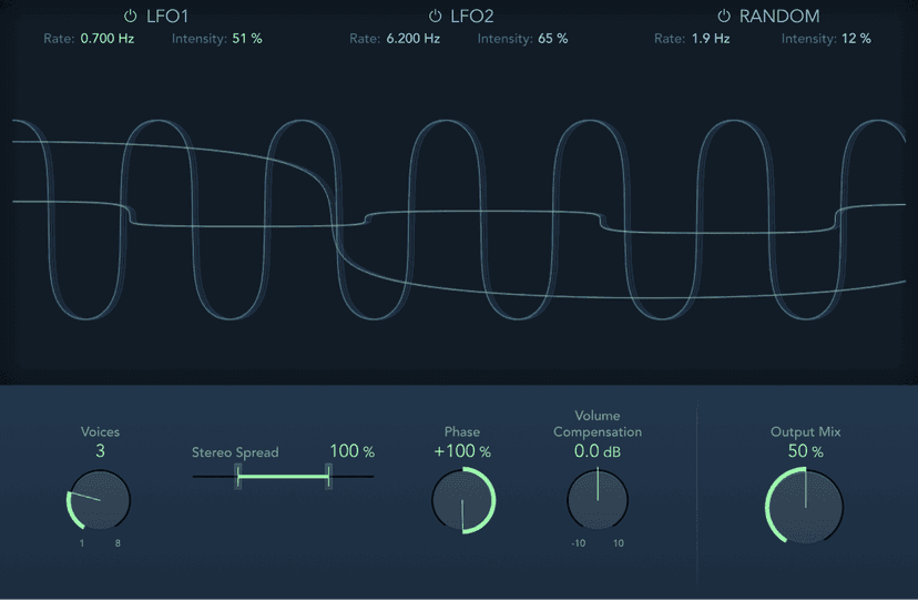
Ensemble parameters
- LFO1/LFO2/Random on/off buttons: Enable or disable LFO 1, LFO 2, or the random LFO independently.
- Rate fields: Set the frequency of LFO 1, LFO 2, and random modulation.
- Intensity fields: Set the amount of LFO 1, LFO 2, and random modulation.
- Graphic display: Shows and lets you edit the shape and intensity of LFO 1, LFO 2, and random modulations. Move the pointer to the left third to adjust LFO 1, the center third to adjust LFO 2, or the right third to adjust the random LFO.
- Modulation is represented by a horizontal line and waveform. The line represents the LFO intensity. The waveform represents the LFO rate. Drag the line or circular handle vertically (or use the corresponding field) to set modulation intensity. Drag the waveform or circular handle horizontally (or use the corresponding field) to set the modulation rate.
- LFO1 parameters: Drag the green handle to set modulation rate and intensity.
- LFO2 parameters: Drag the blue handle to set modulation rate and intensity.
- Random LFO parameters: Drag the white handle to set modulation rate and intensity.
- Voices knob and field: Set the number of chorus instances (voices) generated in addition to the original signal.
- Stereo Spread slider and field: Distribute voices across the stereo or surround field. You can set a value of 200% to artificially expand the stereo or surround base. Note that monaural compatibility may suffer if you do this.Note:When used in surround, the input signal is converted to mono before processing. In essence, you insert the Ensemble effect as a multi-mono instance.
- Phase knob and field: Control the phase relationship between the individual voice modulations. The value you choose here is dependent on the number of voices, which is why it is shown as a percentage value rather than in degrees. The value 100 (or −100) indicates the greatest possible distance between the modulation phases of all voices.
- Volume Compensation knob and field: Compensate for effects signal volume changes caused by adjusting the Voices value.
- Output Mix knob and field: Set the balance between dry and wet signals.
Modulation Delay
Modulation Delay is based on the same principles as Flanger and Chorus effects, but you can set the delay time, allowing both chorus and flanging effects to be generated. It can also be used without modulation to create resonator or doubling effects. The modulation section consists of two LFOs with variable frequencies.
Although rich, combined flanging and chorus effects are possible, the Modulation Delay is capable of producing some extreme modulation effects. These include emulations of tape speed fluctuations and metallic, robot-like modulations of incoming signals.
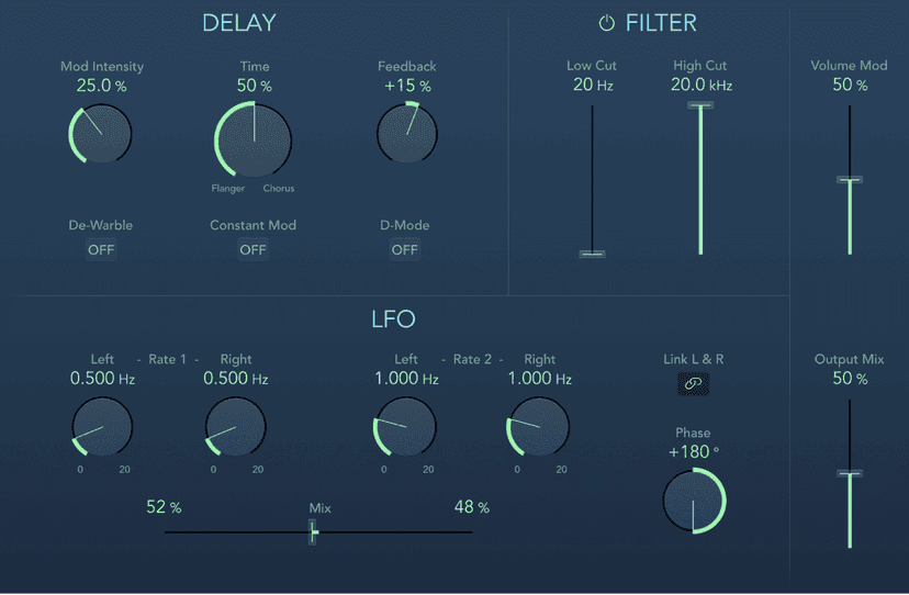
Modulation Delay parameters
- Mod Intensity knob and field: Set the modulation amount.
- Time knob and field: Set the basic delay time. Set to the far left position to create flanger effects, to the center for chorus effects, and to the far right to hear clearly discernible delays.
- Feedback knob and field: Set the amount of effect signal routed back to the input. Use a high Feedback value for strong modulations. If you want to double the signal, don’t use Feedback. Negative values invert the phase of the feedback signal, resulting in more chaotic effects.
- De-Warble button: Turn on to make sure the pitch of the modulated signal remains constant.
- Constant Mod button: Turn on to make sure the modulation width remains constant, regardless of the modulation rate.Note: When Constant Mod is enabled, higher modulation frequencies reduce the modulation width.
- D-Mode button: Turn on to introduce a spatial filtering effect that resembles a well-known vintage processor.Note:Available only in stereo or mono->stereo instances.
- LFO 1/2 Rate knobs and fields: Set the modulation rate for the left and right stereo channels. In surround instances, the center channel is assigned the middle value of the left and right LFO Rate knobs. The other channels are assigned values between the left and right LFO rates.Note: The right LFO Rate knob is available only in stereo and surround instances, and it can be set separately only if the Link L & R button is not enabled.
- Link L & R button: Link the modulation rates of the left and right stereo channels. Adjustment of either Rate knob affects the other channel in stereo instances, or other channels in surround instances.
- Mix slider and fields: Determine the balance between the two LFOs.
- Phase knob and field: Control the phase relationship between individual channel modulations. Available only in stereo and surround instances.
- At 0°, the extreme values of the modulation are achieved simultaneously for all channels.
- At 180° or −180°, you achieve the greatest possible distance between the modulation phases of the channels.
- Note: The Phase parameter is available for use only if the Link L & R button is active.
- Distribution pop-up menu: Choose how phase offsets between individual channels are distributed in the surround field. Choose from: circular, left↔right, front↔rear, random, or new random. Available only in surround instances.Note: When you load a setting that uses the random option, the saved phase offset value is recalled. If you want to randomize the phase setting again, choose new random from the Distribution pop-up menu.
- Filter button: Turn on to introduce an additional allpass filter into the signal path. This filter shifts the phase angle of a signal, influencing its stereo image.
- Low/High Cut sliders and fields: Set the frequency at which the phase shift crosses 90°—the halfway point of the total 180°—for each of the stereo channels. In surround instances, the other channels are automatically assigned values that fall between the two settings.
- Volume Mod slider and field: Determine the impact of LFO modulation on the amplitude of the effect signal.
- Output Mix slider and field: Set the balance between dry and wet signals.
Ringshifter
Ringshifter combines a ring modulator with a frequency shifter effect in a clear, compact interface. Both effects were popular during the 1970s and are currently experiencing a renaissance.
The ring modulator modulates the amplitude of the input signal using either the internal oscillator or a side chain signal. The frequency spectrum of the resulting effect signal equals the sum of, and the difference between, the frequency content in the two original signals. Its sound is often described as metallic or clangorous.
The frequency shifter moves the frequency content of the input signal by a fixed amount and thereby alters the frequency relationship of the original harmonics. The resulting sounds range from sweet and spacious phasing effects to robot-like timbres.
Note: Do not confuse frequency shifting with pitch shifting. Pitch shifting transposes the original signal, leaving its harmonic frequency relationship intact.
The Ringshifter interface consists of six main sections.
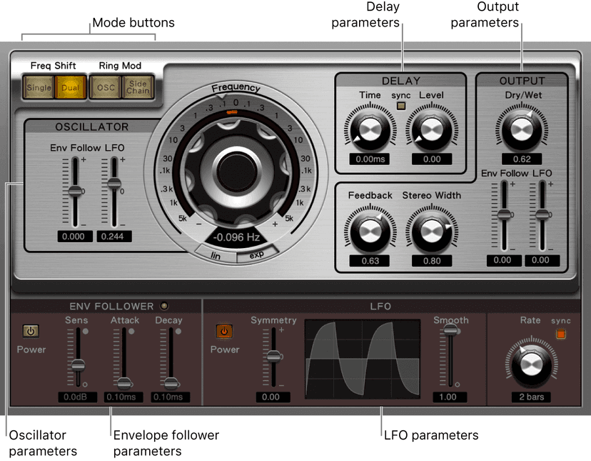
- Mode buttons: Determine whether Ringshifter operates as a frequency shifter or a ring modulator.
- Oscillator parameters: Configure the internal sine wave oscillator, which modulates the amplitude of the input signal in both of the frequency shifter modes as well as in the ring modulator OSC mode.
- Delay parameters: Delay the effect signal.
- Envelope follower parameters: Modulate the oscillator frequency and output signal with an envelope follower.
- LFO parameters: Modulate the oscillator frequency and output signal with an LFO.
- Output parameters: Set feedback, stereo width, and the amount of dry and wet signals.
Do this now
- Put Delay Designer on a snare.
- Create four taps by hand, each at a different time, pan and level.
- Filter the later taps darker than the early ones.
A delay with taps you placed yourself is a rhythm. A delay with a preset is a preset.